Isuzu KB P190. Manual — part 108
4A-16 PROPELLER SHAFT
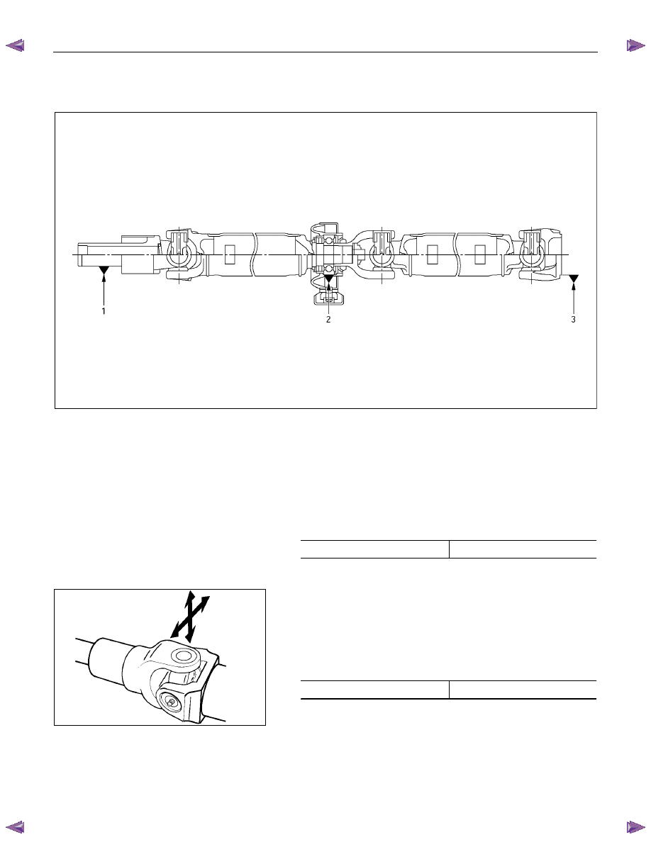
Propeller Shaft Run-Out
401R300005
∗Grease fitting are installed to 4x4 vehicles only
Support 1 of splined yoke, 2 of center bearing and 3 of flange
yoke and check for static run-out by holding the probe of a dial
indicator in contact with the center part of the shaft and turning
the propeller shaft.
If the amount of run-out is beyond the limit value, correct with a
bench press or replace the shaft with a new one.
mm(in)
Limit 1.0
(0.04)
401R300008
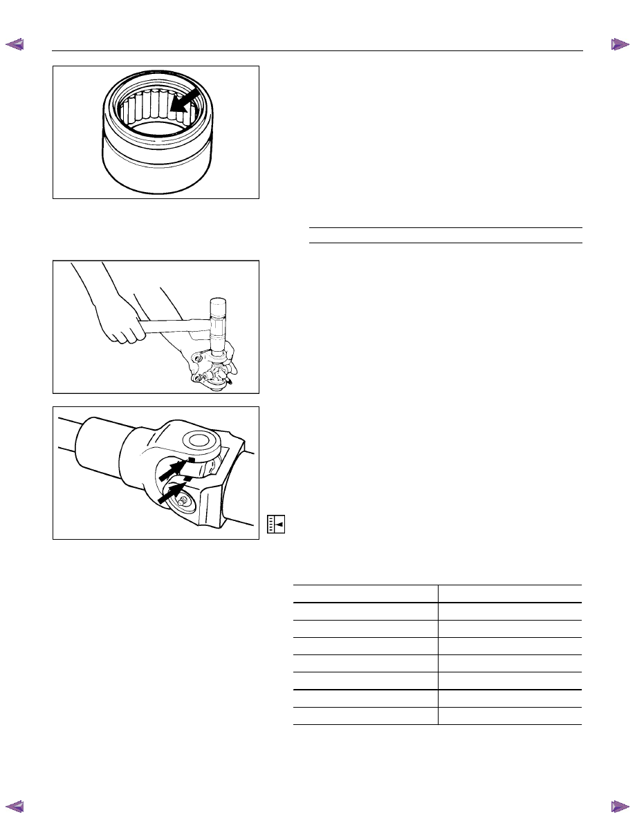
Play in Spider Bearing
(1) Check the spider bearings for wear or damage.
(2) Check the amount of axial and radial play in spider bearing
by moving the yoke back and forth on the spider axes and
shaft axis.
mm(in)
Limit 0.1
(0.004)
If the limit is exceeded, replace the shaft assembly.
PROPELLER SHAFT 4A-17
401RS011
Universal Joint Reassembly
1. Set the propeller shafts.
• Be sure to set the propeller shaft yoke by aligning the
setting marks made during disassembly.
2. Spider
• Be sure to install the spider by aligning the setting marks
made during disassembly.
3. Needle Roller Bearing
1) Apply a molybdenum-disulfide grease or a multi-purpose.
type grease NLGI No.2 to inside of the bearing cap.
Grease Amount
g(oz)
Approx. 1.2 (0.042)
401RS012
2) Using either a mallet (or copper hammer) or a press, install
the needle roller bearing into the yoke so that snap ring can
be installed in its groove.
CAUTION:
•••• The needle roller bearing cannot be installed smoothly
if it is set at an incorrect angle with the flange.
•••• Excessive hammering will damage the needle roller
bearing.
401R300003
3) Align setting marks and join the yokes.
NOTE:
Assemble the spider and spline yoke so that their grease
fittings are arranged on the same side.(4×4)
4. Snap ring
NOTE:
Discard used snap rings and install new ones.
When the bearing cap is in position, select and attach a snap
ring of suitable thickness so that the end play of the spider pin
is held within 0.1mm (0.004in).
mm(in)
Snap ring thickness
Identification color
1.50 (0.059)
Light
Blue
1.53 (0.060)
White
1.56 (0.061)
Pink
1.59 (0.063)
Yellow
1.62 (0.064)
Green
1.65 (0.065)
Brown
1.68 (0.066)
Not
colored
NOTE:
Be sure to use snap rings of the same thickness on both sides.
4A-18 PROPELLER SHAFT
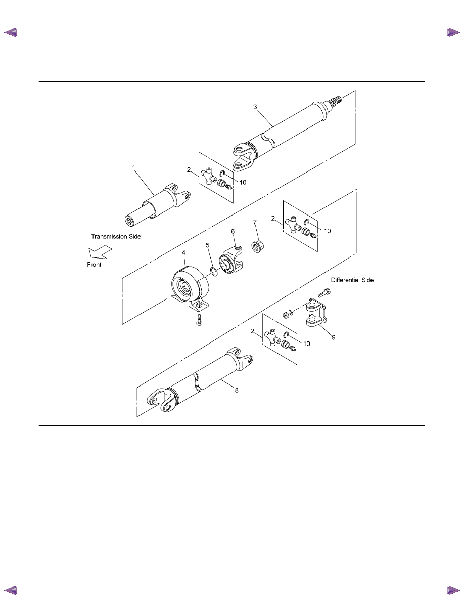
Rear Propeller Shaft Assembly
(4×2, 4×4)
RTW54ALF000101
Legend
1.
Splined
Yoke
2.
Journal
Assembly
3. 1st Tube Assembly
4.
Center
Bearing
5.
Plain
Washer
6.
Center
Yoke
7.
Lock
Nut
8. 2nd Tube Assembly
9.
Flange
Yoke
10.
Snap
Ring
PROPELLER SHAFT 4A-19
Disassembly
1. Disassembly the three portions of the journal assemblies.
2. Remove the splined yoke, the 1st tube assembly with center
bearing, the 2nd tube assembly and the flange yoke.
3. Remove the lock nut.
4. Remove the center yoke, the plain washer the center
bearing and the 1st tube assembly.
Reassembly
1. Install the center bearing on the 1st tube assembly.
Clean the bearing fitting face.
Repack the grease.
Amount of grease
required g(oz)
Approx. 12 (0.42)
2. Install the plain washer and the center yoke.
3. Install the lock nut and tighten it to the specified torque.
Lock nut Torque : 118 N
⋅⋅⋅⋅m (12.0 kgf⋅⋅⋅⋅m/87lb⋅⋅⋅⋅ft)
(1) Discard the flange nut and install a new one.
(2) Stake the outer face of the flange nut against the slot in the
shaft.
4. Install the splined yoke, the 1st tube assembly with center
bearing, the 2nd tube assembly and the flange yoke by
assembling the universal joint.
Нет комментариевНе стесняйтесь поделиться с нами вашим ценным мнением.
Текст