Isuzu KB P190. Manual — part 109
4A-20 PROPELLER SHAFT
Front Propeller Shaft
Removal and Installation
RUW54AMF000201
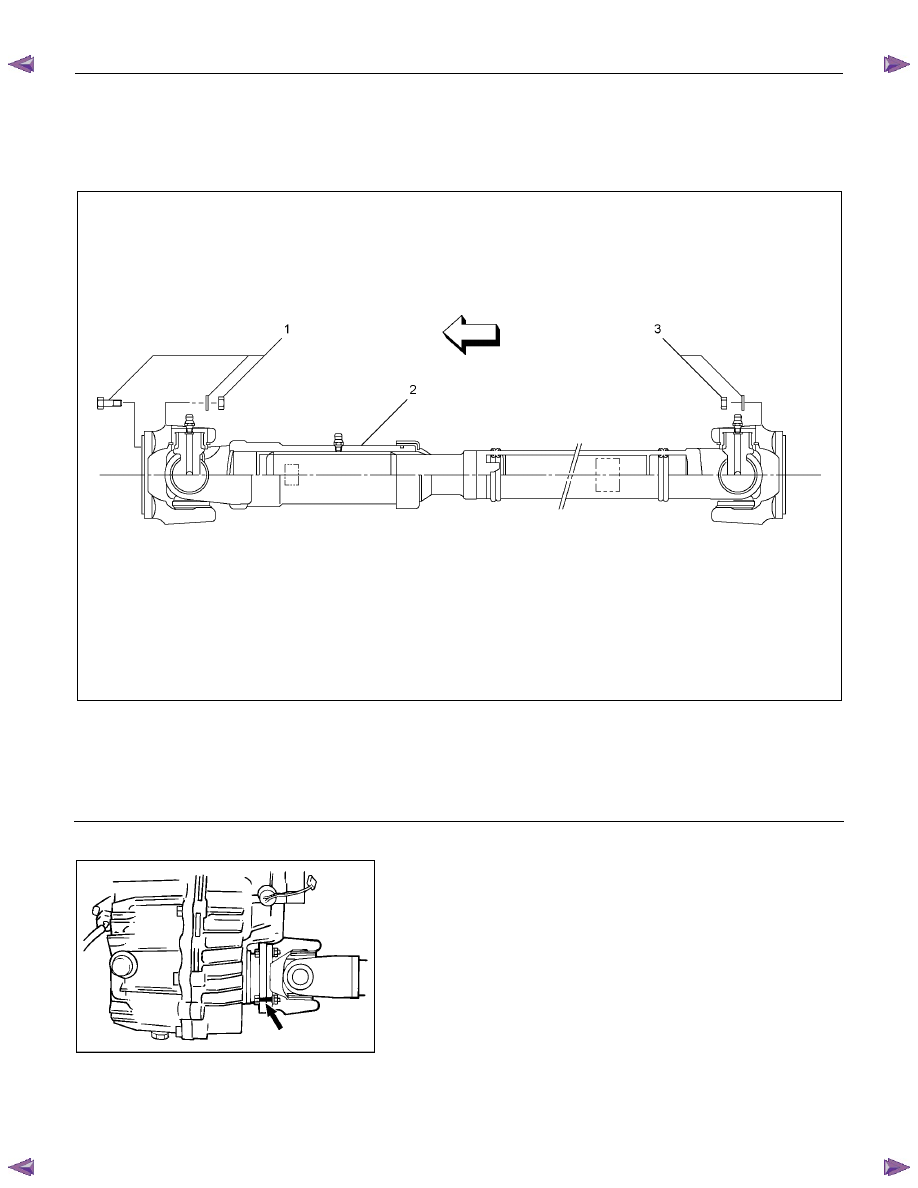
Legend
1. Bolt, Nut and Washer (Front Axle Side)
2. Front Propeller Shaft
3. Nut and Washer (Transfer Side)
401RS020
Removal
1. Jack up the vehicle and support it on the chassis stands.
2. Gear shift lever should be placed in neutral position and
parking brake released.
3. Remove the exhaust and transfer protectors.
NOTE:
Apply alignment marks on the flange at the front propeller shaft
both front and rear side.
4. Remove bolt, nut and washer (Front axle side).
5. Remove bolt, nut and washer (Transfer side).
6. Remove front propeller shaft.

PROPELLER SHAFT 4A-21
Installation
NOTE:
Never install the shaft assembly backwards. Completely
remove the black paint from the connecting surface of flange
coupling on each end of propeller shaft. Clean so that no
foreign matter will be caught in between.
1. Align the mark, which was applied at removal. Install front
propeller shaft and tighten the bolts and nuts to the
specified torque.
Torque: 59 N
⋅⋅⋅⋅m (6.0 kgf⋅⋅⋅⋅m/43 lb⋅⋅⋅⋅ft)
2. Install the exhaust and transfer protectors.
401RS019
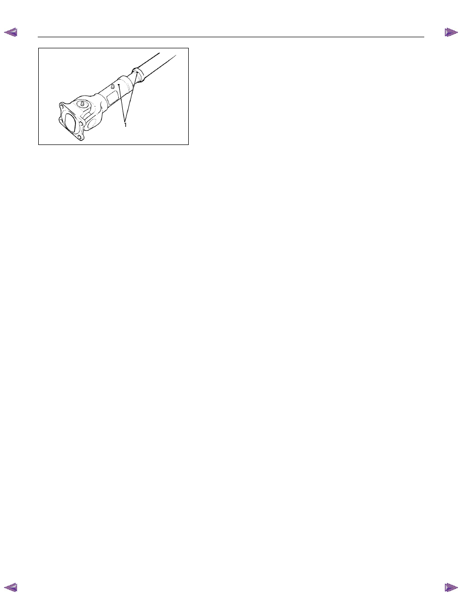
3. After installing the propeller shaft, be sure to apply black
paint (1) to exposed area (other than connecting surface) of
the entire surface of flange coupling.
4A-22 PROPELLER SHAFT
Disassembly
401RW057
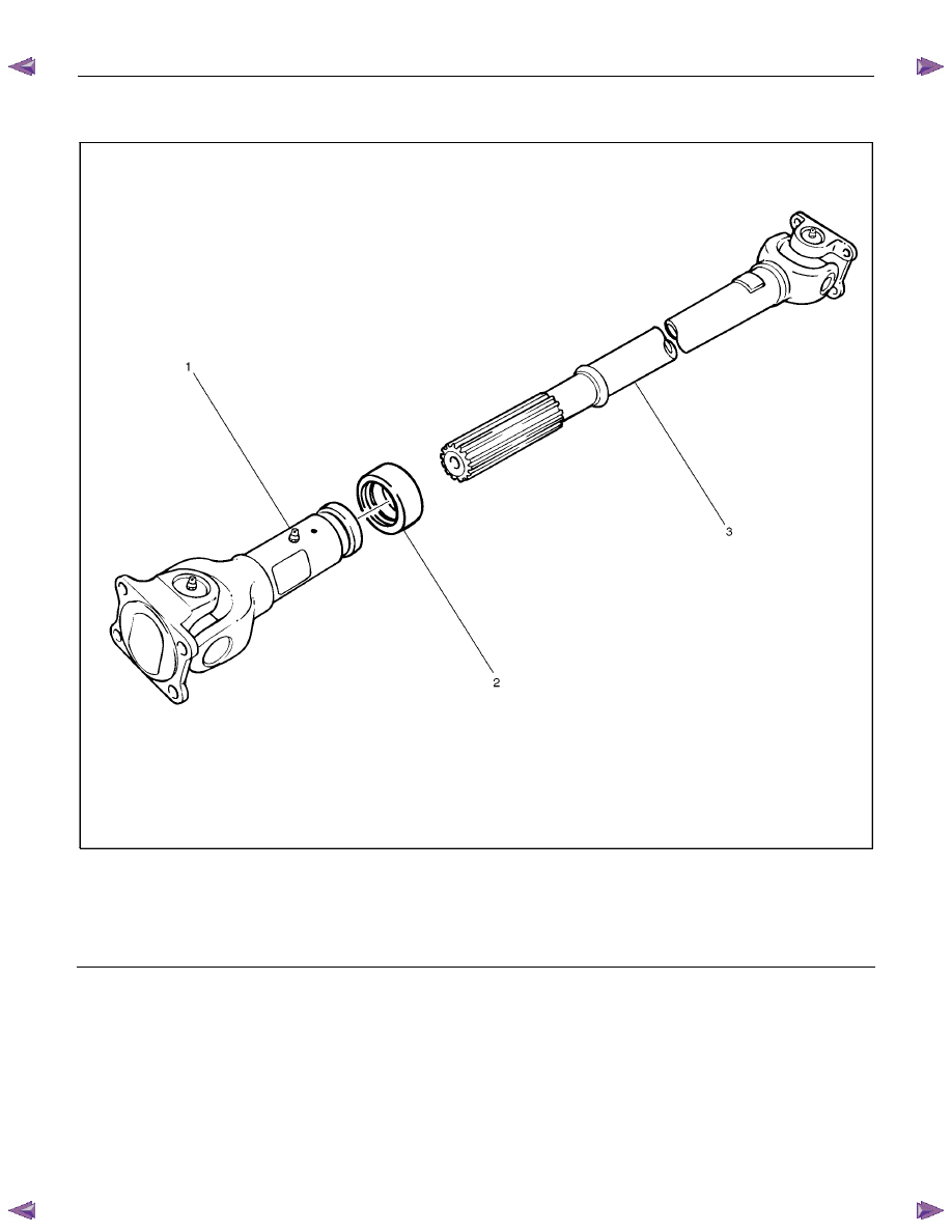
Legend
1.
Sleeve
Yoke
2.
Seal
3.
Tube
Assembly
PROPELLER SHAFT 4A-23
401RW056
1. Apply alignment marks (1) on the sleeve yoke and tube
assembly then remove sleeve yoke.
2. Remove seal.
3. Remove tube assembly.
Нет комментариевНе стесняйтесь поделиться с нами вашим ценным мнением.
Текст