Isuzu KB P190. Manual — part 808
Fuel System – V6
Page 6C – 30
4.7
Fuel Tank Siphon Procedure
• Fuel vapour remains in the modular fuel
pump and sender assembly and fuel lines
that can be spilled during service
operations. Ensure no naked flames or
other ignition sources are nearby. Ensure
all cellular phones (and transmission
devices that may cause any metal objects
to become unintentional receiving
antennas) are switched off.
• Place a dry chemical (Class
B) fire
extinguisher nearby before performing any
on-vehicle service procedures. Failure to
follow these precautions may result in
personal injury.
For an exploded view of fuel tank components, refer Figure 6C – 17.
1
Depressurise the fuel system, refer to 3.4
Fuel System Depressurisation.
2
Reinstall the fuel pump relay, refer to 8A Electrical Body and Chassis.
Disconnecting the battery affects certain
vehicle electronic systems. 1.1
WARNING,
CAUTION and NOTES.
3
Disconnect the negative battery terminal.
4
Remove the fuel filler cap.
N O T E
Lubricate the fuel siphon hose with J36850
TransJel Transmission Assembly Lubricant or
equivalent to aid hose insertion. Use only an
approved lubricant.
5
Install J44284–2 flapper door holder (2) into the fuel
filler neck to hold the door open.
Do not siphon, drain or store fuel into an
open container, due to the possibility of fire
or explosion, or contamination. Always use
and approved fuel storage container.
6
Insert the J45004–1 fuel tank siphon hose (1) into the
fuel tank filler neck and gradually twist it until the tip of
the hose meets the fuel tank check valve (3) and
continues to the bottom of the fuel tank.
7
Use a hand-operated or air-operated pump device to
siphon as much fuel through the fuel fill pipe as
possible.
Figure 6C – 35
Fuel System – V6
Page 6C – 31
Fuel vapour remains in the fuel tank even
when completely empty. Seal all openings in
the fuel tank using suitable material or a
plastic plug. Ensure no naked flames or other
ignition sources are nearby. Ensure all
cellular phones (and transmission devices
that may cause any metal objects to become
unintentional receiving antennas) are
switched off.
Do not use excessive force when removing
the fuel siphon hose from the fuel filler neck.
If the fuel siphon hose gets stuck upon
removal, gently twist and tug the fuel siphon
hose back and forth until it releases.
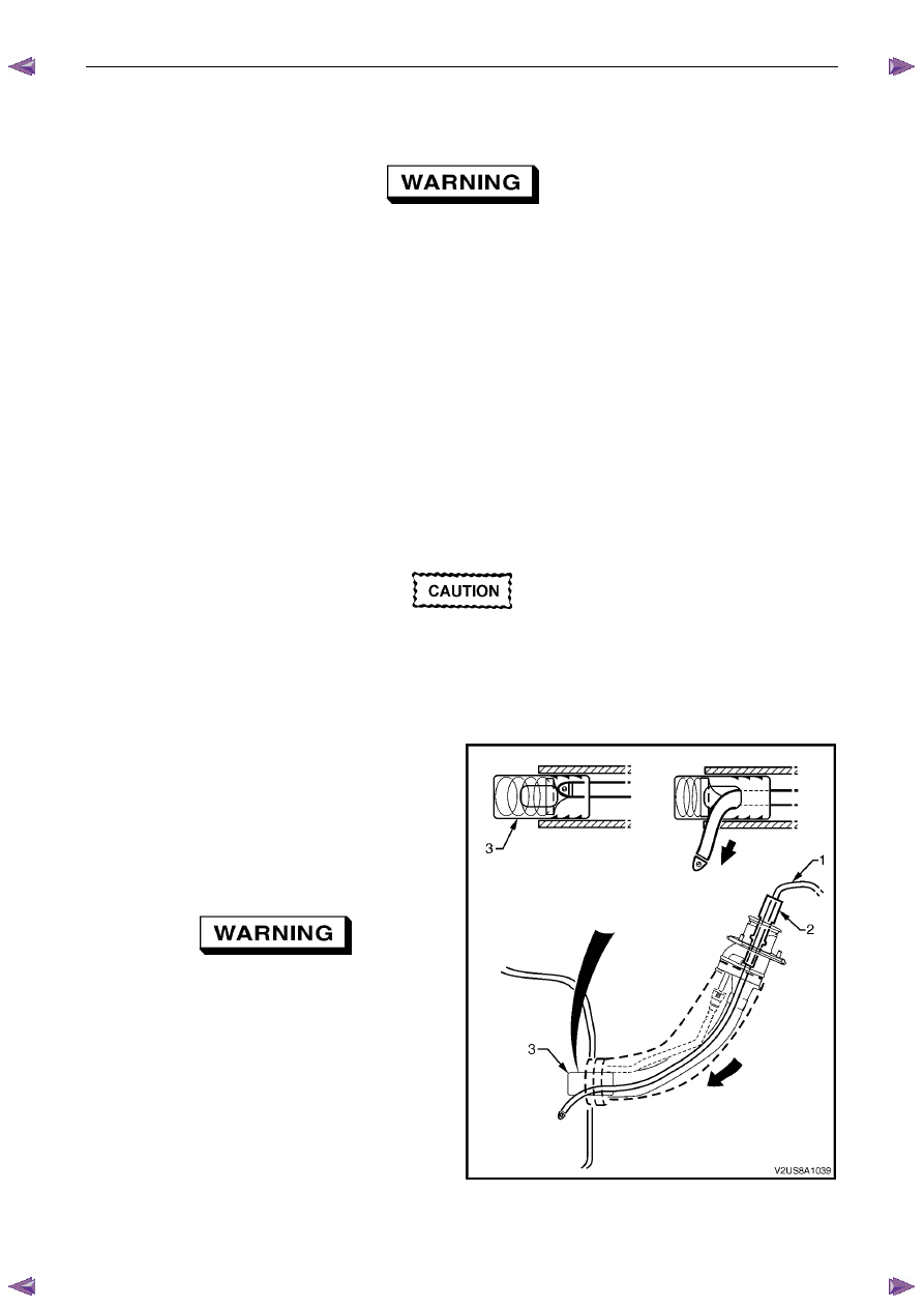
N O T E
• If fuel does not siphon from the fuel tank, the
fuel siphon hose may have entered the fuel
tank through a roof-facing check valve
opening. If required, insert the J45004–1 fuel
siphon hose (1) into the fuel tank filler neck,
refer to Figure 6C – 35, but twist the fuel
siphon hose 90° as it slides down the filler
neck. This enables the fuel siphon hose to
enter the fuel tank through a floor-facing
check valve opening.
• The siphon procedure will not remove all fuel
from the fuel tank. If required, fuel remaining
in the fuel tank may be siphoned out through
the top of the fuel tank, once the modular fuel
pump and sender assembly is removed from
the tank, refer to 4.4
Fuel Tank.
8
Remove the siphon equipment.
Fuel System – V6
Page 6C – 32
4.8
Fuel Filler Cap
The fuel filler cap is a 'screw on' type, with an integrated tightening torque limiting mechanism. When installing the fuel
filler cap, tighten it until a ratcheting (clicking) sound is audible, indicating the fuel filler cap is properly tightened. The fuel
filler cap is tethered to the fuel filler pocket.
Remove
The fuel filler cap requires a quarter of a turn anticlockwise to be removed.
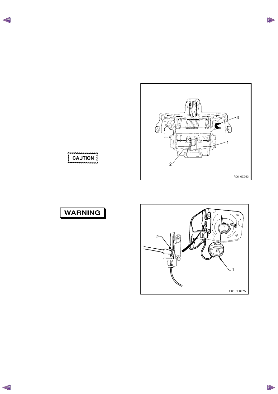
Vacuum and pressure valves are built into the fuel filler cap
which regulate the pressure in the fuel tank and prevent fuel
tank and system damage.
Inspection
Inspect the fuel filler cap and seal for any signs of damage.
Replace the fuel filler cap if found to be defective.
1 Pressure
Valve
2 Vacuum
Valve
3 Seal
Ring
A replacement fuel filler cap must be the
same type as the original. The fuel filler cap
pressure and vacuum valves are specific to a
particular application and must be replaced
with the same type or fuel system damage
may occur.
Figure 6C – 36
If the fuel filler cap needs replacing, use only
a 'screw on' fuel tank filler cap with an
integrated tightening torque limiting
mechanism. Failure to use the correct fuel
tank filler cap can result in a serious
malfunction of the emission control or fuel
system.
1
Untwist and remove the fuel filler cap (2) from the fuel
filler neck opening.
2
Cover the fuel filler opening with a suitable material to
prevent foreign objects from entering the fuel tank.
3
To remove the fuel filler cap tether line use a flat-
bladed screwdriver to prise the tether line fastener (2)
from it’s mounting hole.
N O T E
Check the fuel filler cap for serviceability and
replace if required.
Figure 6C – 37
Reinstall
Reinstallation of the fuel filler cap is the reverse of the removal procedure.
Fuel System – V6
Page 6C – 33
4.9 Fuel
Lines
Remove
• A depressurised fuel system contains fuel
in the fuel filter and fuel lines that can be
spilled during service operations.
• Fuel vapour remains in the fuel tank even
when completely empty. Seal all openings
in the fuel tank using suitable material or a
plastic plug. Ensure no naked flames or
other ignition sources are nearby. Ensure
all cellular phones (and transmission
devices that may cause any metal objects
to become unintentional receiving
antennas) are switched off.
• Place a dry chemical (Class
B) fire
extinguisher nearby before performing any
on-vehicle service procedures. Failure to
follow these precautions may result in
personal injury.
• Wear safety glasses when using
compressed air. Do not blow compressed
air onto any body part.
1
Remove the fuel pump relay, refer to 8A Electrical Body and Chassis.
2
Depressurise the fuel system, refer to 3.4
Fuel System Depressurisation.
Never drain or store fuel into an open
container, due to the possibility of fire or
explosion.
3
Raise the vehicle, preferably on a hoist, refer to 0A General Information.
Before proceeding, clean all traces of dirt and
other foreign material from the fuel lines.
4
Use compressed air to ensure that all dirt and foreign materials are removed from all fuel connections before the
parts are disconnected.
5
If required, remove the stone guard, refer to Figure 6C – 17 and fuel lines. Use the following illustrations showing
the fuel line layout and location of other items relating to the fuel system as a guide, also refer to 4.1 Fuel Lines
And Quick Connect Fittings and 4.6
Evaporative Emission Control Canister.
Нет комментариевНе стесняйтесь поделиться с нами вашим ценным мнением.
Текст