Isuzu KB P190. Manual — part 807
Fuel System – V6
Page 6C – 26
Fuel vapour remains in the fuel tank even
when completely empty. Seal all openings in
the fuel tank using suitable material or a
plastic plug. Ensure no naked flames or other
ignition sources are nearby. Ensure all
cellular phones (and transmission devices
that may cause any metal objects to become
unintentional receiving antennas) are
switched off.
15
Place a suitable material over the opening in the fuel tank to prevent any foreign matter from entering the fuel
system.
Fuel Level Sender Assembly
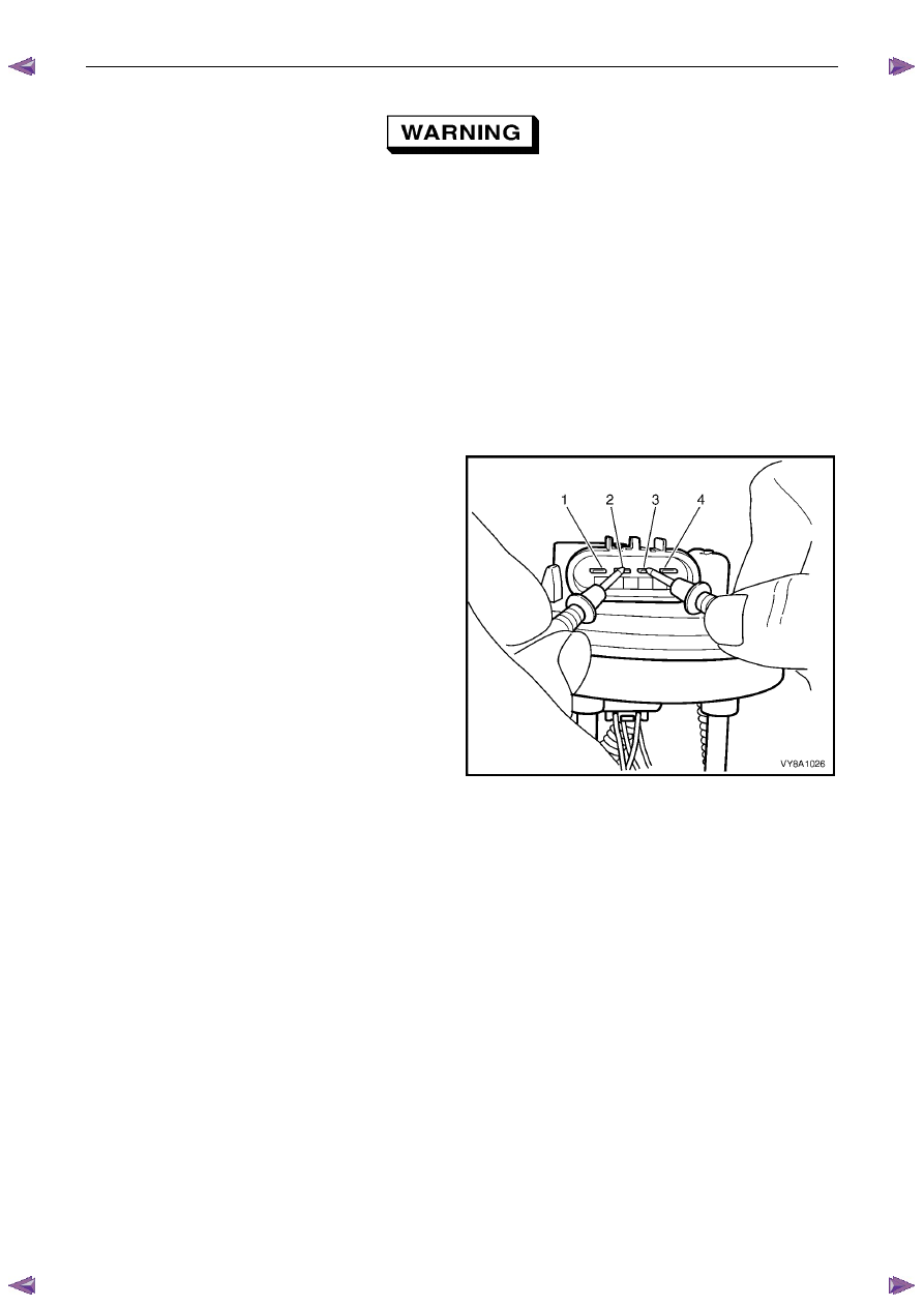
Test
1
Measure the resistance across terminals 2 and 3 of
the fuel pump connector. Take the following
measurements:
a
With the float arm assembly in the empty
position, the resistance should be approximately
250
Ω.
b
With the float arm assembly rotated to the full
position, the resistance should be approximately
40
Ω.
2
If the resistance at either of these positions is not
within tolerance, replace the modular fuel pump and
sender assembly.
Figure 6C – 27
Reinstall
Reinstallation of the modular fuel pump and sender assembly is the reverse of the removal procedure, noting the
following:
1
Fit a new O-ring (3) to the modular fuel pump and sender assembly.
2
Install the modular fuel pump and sender assembly into the fuel tank, taking care not to damage the fuel sender
float or arm.
3
Ensure the locator in the pump cover engages in the slot in the fuel tank opening.
4
Using tool No. AU469 and a half-inch breaker bar, install the modular fuel pump and sender assembly cover
retainer lock ring by turning it clockwise.
5
Refit the three quick connect fittings.
Fuel System – V6
Page 6C – 27
4.6
Evaporative Emission Control Canister
Remove
1
Raise the vehicle on a hoist to give access to the evaporative emission control canister, located above the spare
wheel , refer to 0A General Information.
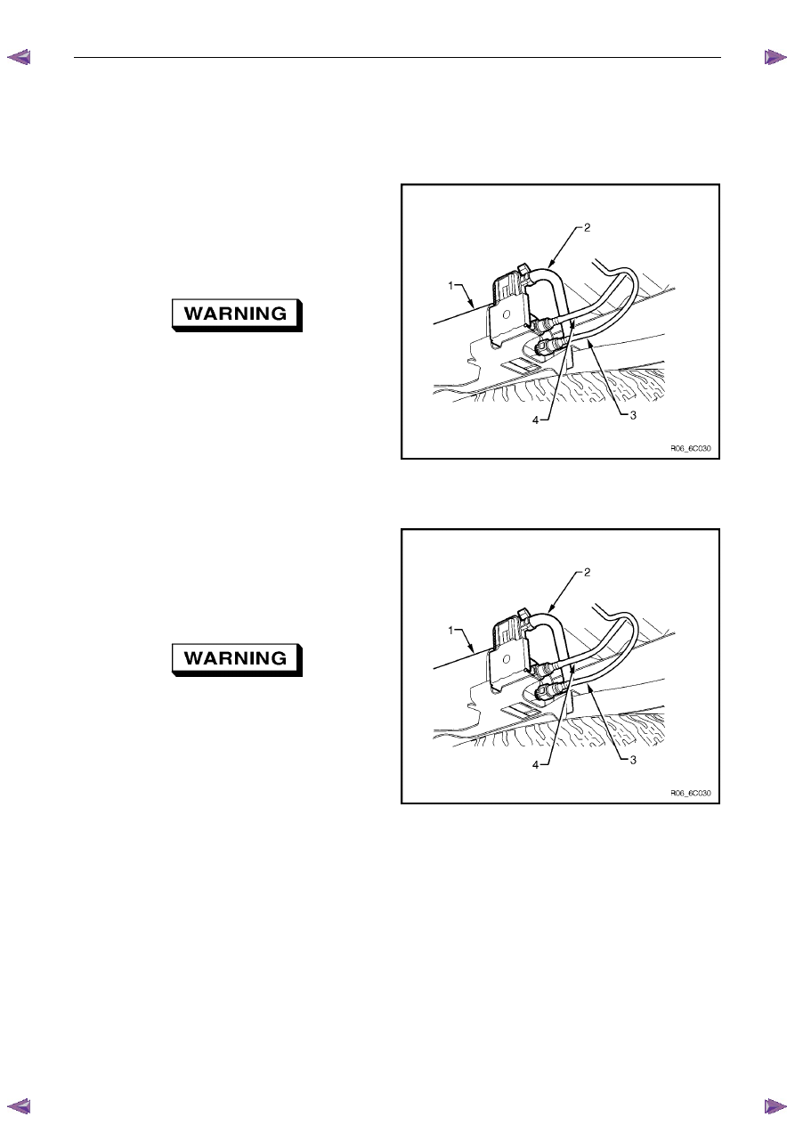
2
Disconnect the evaporative emission control canister
purge line (3) by using the following procedure:
a
Grasp both sides of the quick-connect fitting.
Twist the connector 1/4 turn in each direction in
order to loosen any dirt within the quick-connect
fitting.
Wear safety glasses when using compressed
air. Do not blow compressed air onto any
body part.
b
Using compressed air, blow any dirt out of the
quick-connect fitting.
c
Grasp the quick-connect fitting and push it
towards the canister.
d
Squeeze the quick-connect fitting to release the
retaining tabs, then pull back on the connector to
remove the canister purge line from the canister.
Figure 6C – 28
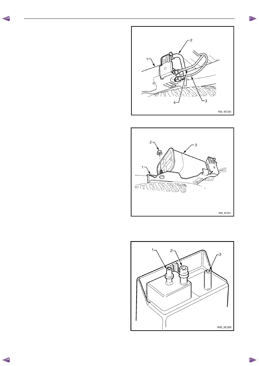
3
Disconnect the fuel tank vent line (4) by using the
following procedure:
a
Grasp both sides of the quick-connect fitting.
Twist the connector 1/4 turn in each direction in
order to loosen any dirt within the quick-connect
fitting.
Wear safety glasses when using compressed
air. Do not blow compressed air onto any
body part.
b
Using compressed air, blow any dirt out of the
quick connect fitting.
c
Grasp the quick-connect fitting and push it
towards the canister.
d
Squeeze the quick-connect fitting to release the
retaining tabs, then pull back on the connector to
remove the tank vent line from the canister.
Figure 6C – 29
Fuel System – V6
Page 6C – 28
4
Remove the canister vent line (2) from the canister (1)
by twisting and pulling it off.
Refer to 4.1 Fuel Lines And Quick Connect Fittings for
further information.
Figure 6C – 30
5
Remove the canister retaining nut (2).
6
Remove the canister from the retaining stud and then
slide the canister (3) out of the retaining bracket (1).
Figure 6C – 31
Service Check
1
Remove the canister.
2
Shake the canister. There should be no audible sound
of carbon movement.
3
Using low pressure compressed air (20–35 kPa), blow
into the tank vent port (3). Check that air flows freely
from the canister vent port (1). Block the canister vent
port (1); air should flow from the canister purge
port (2).
4
If airflow through the canister vent port (1) is limited,
clean the atmospheric filter by blocking off the fuel
tank vent port (3) and blow compressed air at
approximately 300 kPa through the canister purge
port (2).
5
Check airflow through the filter as in step 3. If airflow
through the canister vent port (1) is still limited, replace
the canister.
Figure 6C – 32
Fuel System – V6
Page 6C – 29
6
Block the canister vent port (1) and the canister purge port (2). Apply low-pressure compressed air
(20–35 kPa) to the tank vent port (3). If any air leaks from the canister (that is, around the ports or seams), replace
the canister.
N O T E
In dusty areas, an alternative is to block the
canister purge port
(2). Blow air through the
canister vent
(1) port and check that air is
expelled through the tank vent port (3).
Reinstall
Reinstallation of the evaporative emission control canister is the reverse of the removal procedure.
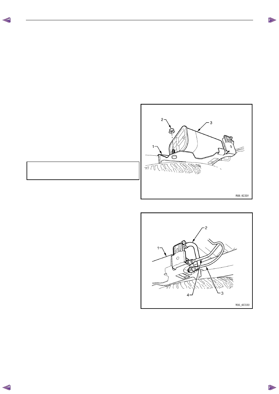
1
Reinstall the canister into the retainer (1) and over the
retaining stud.
2
Reinstall the canister retaining nut (2), then hand-
tighten.
3
Ensure the canister is located correctly and tighten the
canister retaining nut (2) to the specified torque.
Evaporative emission control canister
retaining nut
torque specification . . . . . . . . . .2.0 – 5.0 Nm
Figure 6C – 33
4
Reinstall the canister vent line (2).
5
Align the canister purge line quick-connect (3) with the
canister purge line port. Push the quick-connect firmly
onto the port.
6
Align the fuel tank vent line quick-connect (4) with the
fuel tank vent port. Push the quick-connect firmly onto
the port.
7
After installation, pull on each quick-connect to ensure
the connections are secure and locked in position.
Figure 6C – 34
Нет комментариевНе стесняйтесь поделиться с нами вашим ценным мнением.
Текст