Isuzu KB P190. Manual — part 898
Charging System – V6
Page 6D1-1-5
•
Death or injury to other people in or near the workplace area, and / or
•
Death or injury to the driver / or passenger(s) of the vehicle or other people, if the vehicle has been improperly
repaired.
CAUTION defined
A CAUTION statement immediately precedes an operating procedure or maintenance practice which, if not correctly
followed, could result in damage to or destruction of equipment, or corruption of data. If a CAUTION statement is
ignored, the following consequences may occur:
•
Damage to the vehicle,
•
Unnecessary vehicle repairs or component replacement,
•
Faulty operation or performance of any system or component being repaired,
•
Damage to any system or components which depend on the proper operation of the system or component being
repaired,
•
Faulty operation or performance of any systems or components which depend on the proper operation or
performance of the system or component under repair,
•
Damage to fasteners, basic tools or special tools and / or
•
Leakage of coolant, lubricant or other vital fluids.
NOTE defined
A NOTE statement immediately precedes or follows an operating procedure, maintenance practice or condition that
requires highlighting. A NOTE statement also emphasises necessary characteristics of a diagnostic or repair procedure.
A NOTE statement is designed to:
•
Clarify a procedure,
•
Present additional information for accomplishing a procedure,
•
Give insight into the reasons for performing a procedure in the recommended manner, and / or
•
Present information that gives the technician the benefit of past experience in accomplishing a procedure with
greater ease.
1.3 System
Operation
Operation
With the ignition switch in the ON position and the engine at rest, current is supplied via the regulator to generator
connector E-4 pin 1 and to the engine control module ECM connector E-60 pin 43. This initiates current flow (within the
regulator) from the generator connection P-9, to the brushes and rotor winding, to ‘excite’ the circuit.
The current in the rotor winding creates magnetic fields between adjacent rotor poles.
With the engine running, the rotor spins, the stator windings cut through this field and induce voltage. As the engine
speed is increased, this induced voltage increases. Current then flows through the three-phase diode bridge in the
rectifier to convert the AC voltage to DC. This is supplied to the generator connector P-9 output and then to the battery
terminal via fuse SBF1.
The regulator monitors the voltage to the battery. When this voltage reaches approximately 14.5 V, the regulator opens
the circuit through the rotor winding, causing the generator output voltage to drop. When the regulator senses a voltage
below a preset voltage, the regulator closes the circuit through the rotor winding and voltage to the battery again
increases. This cycle repeats very rapidly.
Charging System – V6
Page 6D1-1-6
Alternator Warning
N O T E
All generator faults are displayed as
Check Alternator Warning on the instrument
cluster MFD, refer to 8A Electrical Body and
Chassis.
The ECM monitors the voltage on connector E-60 pin 21 and pin 43.
The voltage at the generator connector E-4 pin 2 will remain low when a fault condition is detected in the generator or
associated external circuits. The voltage remains low (while the ignition switch is on) until the fault is repaired.
N O T E
For more information on the alternator warning
refer to 8A Electrical Body and Chassis.
Fault conditions include the following:
•
open circuit or excessive voltage drop in circuit 1,
•
open circuit in the generator phase connection,
•
overcharging conditions,
•
short circuit in the regulator output stage,
•
open circuit in the rotor winding,
•
poor contact between the rectifier and the regulator, and / or
•
high resistance in the fusible link assembly.
Charging System – V6
Page 6D1-1-7
2 Diagnosis
2.1
Diagnostic General Information
Basic Diagnostic Tools Required
Use of incorrect electrical circuit diagnostic
tools when performing the generator
diagnostic procedures could result in
incorrect diagnostic results or damage to
components.
The following electrical circuit testing tools are required to perform the diagnostic procedures detailed in this Section:
•
digital multimeter with 10 mega ohms impedance, and
•
connector test adapter kit Tool No. KM609.
For further information on the use of these tools, refer to 8A Electrical Body and Chassis.
2.2
Tech 2 Data List
The Tech 2 displays the status of certain charging system parameters.
To view the data list:
1
Connect Tech 2 to the DLC.
2
On Tech 2 select:
Engine / V6 Engine / Data Display / Data List / Electrical/Theft Data.
Tech 2 Parameter
Units Displayed
Typical Display Values
Alternator L Terminal D
Percentage
Various
2.3
Diagnostic Systems Check
Step Action
Yes
No
1
1
Connect Tech 2 to the DLC.
2
Ignition ON, engine OFF.
3
On Tech 2 select:
Engine / V6 Engine / Diagnostic Trouble codes / Read
DTC’s.
Are there any set DTC’s?
Go to the
appropriate DTC
table in 6C1-2
Engine
Management – V6 –
Diagnostics.
Refer to 2.5
Charging
System Inoperative
/ Malfunctioning
Reference to following information will assist when diagnosing charging circuit faults:
•
for battery testing, refer to 6D1-3 Battery – V6,
•
for wiring diagram details, refer to Figure 6D1-1 2, and
•
for electrical component locations, refer to 8A Electrical Body and Chassis.
Charging System – V6
Page 6D1-1-8
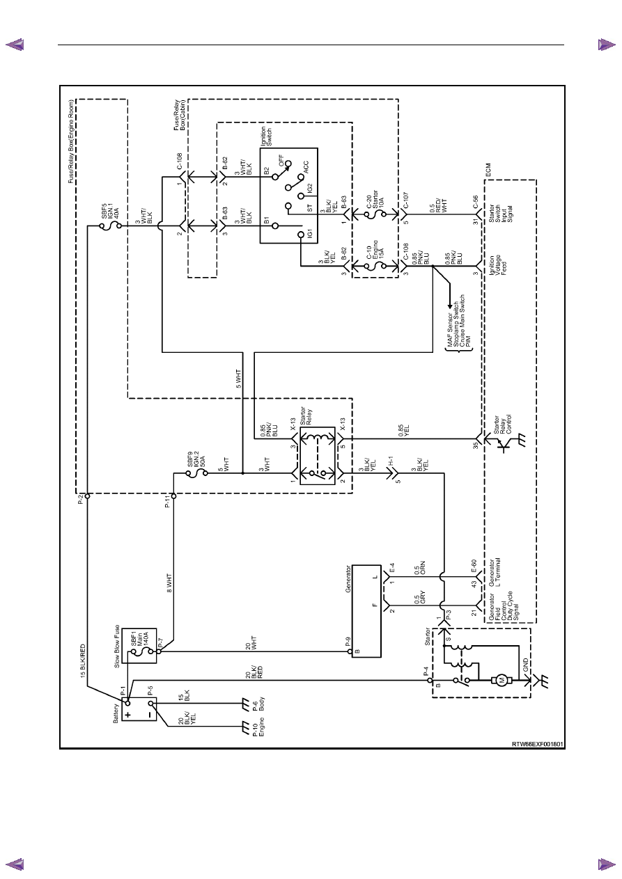
2.4 Wiring
Diagram
Figure 6D1-1 2
Нет комментариевНе стесняйтесь поделиться с нами вашим ценным мнением.
Текст