Isuzu KB P190. Manual — part 897

Charging System – V6
Page 6D1-1-1
6D1-1
Charging System – V6
A T T E N T I O N
Before performing any service operations or other procedure described in this Section, refer to
1.2
WARNING, CAUTION and NOTES for correct workshop practices with regard to safety and / or
property damage.
1
General Information . . . . . . . . . . . . . . . . . . . . . . . . . . . . . . . ...3
1.1
Components . . . . . . . . . . . . . . . . . . . . . . . . . . . . . . . . . . . . . . ... 3
Generator. . . . . . . . . . . . . . . . . . . . . . . . . . . . . . . . . . . . . . . . 3
Generator Types . . . . . . . . . . . . . . . . . . . . . . . . . . . . . . . . . . . . 3
Voltage Regulator . . . . . . . . . . . . . . . . . . . . . . . . . . . . . . . . . . . . .. 4
1.2
WARNING, CAUTION and NOTES. . . . . . . . . . . . . . . . . . . . . . . . . . . . . . . 4
Definition of WARNING, CAUTION and NOTE Statements. . . . . . . . . . . . . . . . . . . . . 4
WARNING defined . . . . . . . . . . . . . . . . . . . . . . . . . . . . . . . . . . . . 4
CAUTION defined . . . . . . . . . . . . . . . . . . . . . . . . . . . . . . . . . . . .. 5
NOTE defined . . . . . . . . . . . . . . . . . . . . . . . . . . . . . . . . . . . . . 5
1.3
System Operation . . . . . . . . . . . . . . . . . . . . . . . . . . . . . . . . . . . . .. 5
Operation . . . . . . . . . . . . . . . . . . . . . . . . . . . . . . . . . . . . . . ... 5
Alternator Warning . . . . . . . . . . . . . . . . . . . . . . . . . . . . . . . . . . . . 6
2
Diagnosis . . . . . . . . . . . . . . . . . . . . . . . . . . . . . . . . . . . . 7
2.1
Diagnostic General Information . . . . . . . . . . . . . . . . . . . . . . . . . . . . . . ... 7
Basic Diagnostic Tools Required. . . . . . . . . . . . . . . . . . . . . . . . . . . . . . . 7
2.2
Tech 2 Data List . . . . . . . . . . . . . . . . . . . . . . . . . . . . . . . . . . . . . . 7
2.3
Diagnostic Systems Check . . . . . . . . . . . . . . . . . . . . . . . . . . . . . . . . ... 7
2.4
Wiring Diagram . . . . . . . . . . . . . . . . . . . . . . . . . . . . . . . . . . . . . .. 8
2.5
Charging System Inoperative / Malfunctioning . . . . . . . . . . . . . . . . . . . . . . . . ... 9
Diagnostic Table Notes . . . . . . . . . . . . . . . . . . . . . . . . . . . . . . . . . .. 9
Diagnostic Table 120A Generator. . . . . . . . . . . . . . . . . . . . . . . . . . . . . .. 9
3
Minor Service Operations . . . . . . . . . . . . . . . . . . . . . . . . . . . . . 10
3.1
Safety Precautions. . . . . . . . . . . . . . . . . . . . . . . . . . . . . . . . . . . ... 10
3.2
Maintenance . . . . . . . . . . . . . . . . . . . . . . . . . . . . . . . . . . . . . . . 10
Regular Checks. . . . . . . . . . . . . . . . . . . . . . . . . . . . . . . . . . . . . 10
Lubrication . . . . . . . . . . . . . . . . . . . . . . . . . . . . . . . . . . . . . ... 10
3.3
On-vehicle Testing. . . . . . . . . . . . . . . . . . . . . . . . . . . . . . . . . . . ... 11
Generator On-vehicle Checks. . . . . . . . . . . . . . . . . . . . . . . . . . . . . . . . 11
Prerequisites . . . . . . . . . . . . . . . . . . . . . . . . . . . . . . . . . . . . . 11
Generator Test . . . . . . . . . . . . . . . . . . . . . . . . . . . . . . . . . . . . . 11
Charging Circuit Voltage Drop Test . . . . . . . . . . . . . . . . . . . . . . . . . . . . ... 13
Prerequisites . . . . . . . . . . . . . . . . . . . . . . . . . . . . . . . . . . . . . 13
Voltage Drop Test . . . . . . . . . . . . . . . . . . . . . . . . . . . . . . . . . . . 13
4
Major Service Operations . . . . . . . . . . . . . . . . . . . . . . . . . . . . . 15
4.1
Generator. . . . . . . . . . . . . . . . . . . . . . . . . . . . . . . . . . . . . . . .. 15
Remove . . . . . . . . . . . . . . . . . . . . . . . . . . . . . . . . . . . . . . . . . 15
Reinstall. . . . . . . . . . . . . . . . . . . . . . . . . . . . . . . . . . . . . . . . 16
4.2
Generator Mounting Bracket . . . . . . . . . . . . . . . . . . . . . . . . . . . . . . . .. 17
Remove . . . . . . . . . . . . . . . . . . . . . . . . . . . . . . . . . . . . . . . . . 17
Reinstall. . . . . . . . . . . . . . . . . . . . . . . . . . . . . . . . . . . . . . . . 17
Charging System – V6
Page 6D1-1-2
4.3
Drive Belt Routing. . . . . . . . . . . . . . . . . . . . . . . . . . . . . . . . . . . . 18
Without Air Conditioning . . . . . . . . . . . . . . . . . . . . . . . . . . . . . . . . . 18
6
Specifications . . . . . . . . . . . . . . . . . . . . . . . . . . . . . . . . . ...19
7
Torque Wrench Specifications. . . . . . . . . . . . . . . . . . . . . . . . . . . 20
8
Special Tools . . . . . . . . . . . . . . . . . . . . . . . . . . . . . . . . . . 21
Charging System – V6
Page 6D1-1-3
1 General
Information
1.1 Components
Generator
The Mitsubishi generator can be identified visually by its two lower and one upper mounting lugs.
It is mounted to the lower right-hand side of the engine block. It is driven by the same drive belt that drives other engine
ancillaries and requires no periodic drive belt adjustment.
The generator has three phases, incorporating a rotor with six pole pairs fitted and two internal cooling fans; one on the
drive-end and one on the slip-ring end. The rotor is supported by ball bearings in both the drive and slip-ring end
housings. Surrounding the rotor is a stator, which has a three phase delta connected output winding construction on a
ring shaped lamination pack.
The output of the stator winding is rectified by eight diodes that are contained within the slip-ring end housing. Excitation
current is supplied to the rotor field coil via the voltage regulator, the brushes and slip-rings. The electronic voltage
regulator requires no adjustment in service.
The generator has four external connections (refer to Figure 6D1-1 1):
•
Generator – Terminal P-9 to the battery positive terminal P-1 via fuse SBF1,
•
Generator – E-4 pin 1 to the ECM connection E-60 pin 43 – regulator monitoring,
•
Generator – E-4 pin 2 to the ECM connection E60 pin 21 – battery voltage sensing, and
•
ground connection via the installation bolts.
Generator Types
The vehicle is fitted with a 120 amp generator.
Charging System – V6
Page 6D1-1-4
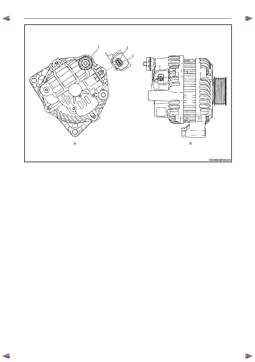
Figure 6D1-1 1
Legend
A
Rear View of Generator
B
Side View of Generator
1
Generator –Terminal P-9
2
Generator – E-4 pin 2
3
Generator – E-4 pin 1
Voltage Regulator
The electronic voltage regulator requires no adjustment in service.
1.2
WARNING, CAUTION and NOTES
This Section contains various WARNINGS, CAUTIONS and NOTE statements that you must observe carefully to reduce
the risk of death or injury during service, repair procedures or vehicle operation. Incorrect service or repair procedures
may damage the vehicle or cause operational faults. WARNINGS, CAUTION and NOTE statements are not exhaustive.
HOLDEN LTD can not possibly warn of all the potentially hazardous consequences of failure to follow these instructions.
Definition of WARNING, CAUTION and NOTE Statements
Diagnosis and repair procedures in this Section contain both general and specific WARNING, CAUTION and NOTE
statements. HOLDEN LTD is dedicated to the presentation of service information that helps the technician to diagnose
and repair the systems necessary for proper operation of the vehicle. Certain procedures may present a hazard to the
technician if they are not followed in the recommended manner. WARNING, CAUTION and NOTE statements are
designed to help prevent these hazards from occurring, but not all hazards can be foreseen.
WARNING defined
A WARNING statement immediately precedes an operating procedure or maintenance practice which, if not correctly
followed, could result in death or injury. A WARNING statement alerts you to take necessary action or not to take a
prohibited action. If a WARNING statement is ignored, the following consequences may occur:
•
Death or injury to the technician or other personnel working on the vehicle,
Нет комментариевНе стесняйтесь поделиться с нами вашим ценным мнением.
Текст