Isuzu KB P190. Manual — part 1323

8A-354 ELECTRICAL-BODY AND CHASSIS
Installation
To Install, follow the removal steps in the reverse order.
FUEL GAUGE UNIT
Removal
Dismount the fuel tank first, then remove the fuel gauge unit.
1. Remove the rear inner liner -LH
• Remove the clip
2. Remove the filler neck.
• Remove the screw
3. Remove the ground with cable.
4. Remove the fuel tank band.
• Disconnect fuel line quick connectors.
5. Remove the fuel gauge unit from the fuel tank.

ELECTRICAL-BODY AND CHASSIS 8A-355
Installation
Follow the removal procedure in the reverse order to install the
fuel gauge unit.
Pay close attention to the important points mentioned in the
following paragraphs.
Rubber Seal
Be absolutely sure that the fuel gauge unit rubber seal is
correctly seated.
Connector
Be absolutely sure that the fuel gauge unit connector is
securely connected.
This will prevent a poor contact and an open circuit.
VEHICLE SPEED SENSOR (INSTALLED
ON THE TRANSMISSION)
Removal
1. Disconnect the connector.
2. Remove the vehicle speed sensor body by rotating it.
Installation
To Install, follow the removal steps in the reverse order, noting
the following point.
Tighten the vehicle speed sensor to the specified torque.
Vehicle Speed Sensor Tightening Torque
N
⋅m (kg⋅m/lb.ft)
25
± 4.9 (2.5 ± 0.5/18 ± 3.6)

8A-356 ELECTRICAL-BODY AND CHASSIS
INSPECTION AND REPAIR
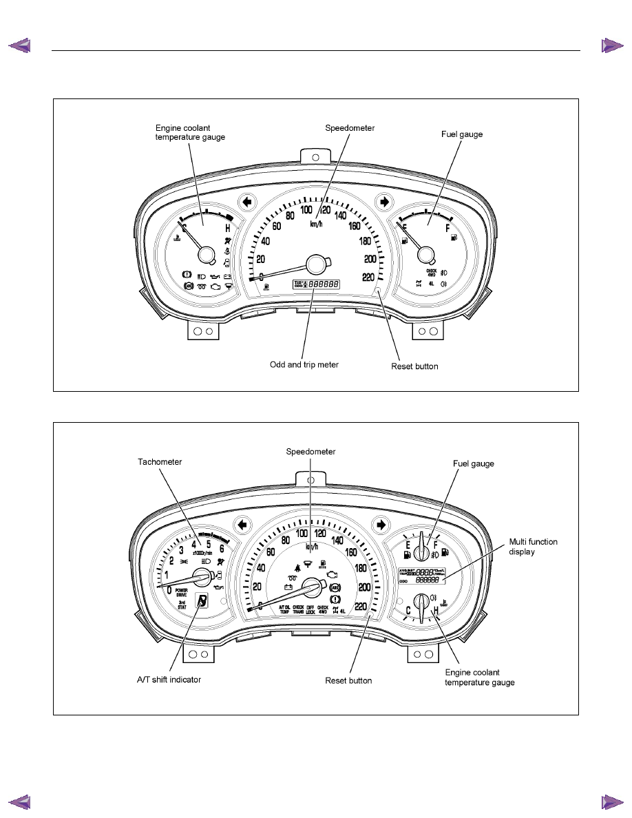
METER AND INDICATOR LIGHT LAYOUT
Without tachometer (4JJ1-TC/4JK1-TC)
RTW78AMF000501
With tachometer (4JJ1-TC/4JK1-TC)
RTW78AMF000101
ELECTRICAL-BODY AND CHASSIS 8A-357
Without tachometer (4JA1T(L)/4JH1-TC)
RTW78AMF000401
With tachometer (4JA1T(L)/4JH1-TC)
RTW78AMF000201
Нет комментариевНе стесняйтесь поделиться с нами вашим ценным мнением.
Текст