Isuzu KB P190. Manual — part 1322
8A-350 ELECTRICAL-BODY AND CHASSIS
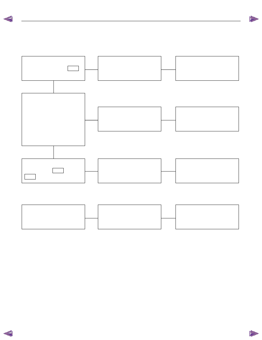
FUEL GAUGE AND FUEL TANK UNIT (HFV6)
1. No fuel level indicates at all
Checkpoint
Trouble
Cause
Countermeasure
Replace the tank unit
Open circuit inside the tank
unit
NG
Thermo unit malfunction
Replace the case baseboard
assy
Fuel gauge function
1. Disconnect the tank unit
connector then connect
3.4W bulb to wire harness
side
2. Check indicating point
when starter SW. is ON
position (Fuel level should
indicate)
Gauge malfunction
Repair open circuit or
connector contact
Continuity between
connectors 17
B23
and 17
B96
Open circuit or poor connector
contact
NG
NG
OK
OK
PIM (Tank unit) continuity
between connector 17
B96
and ground
2. Fuel gauge gives incorrect readings in all ranges
Replace the tank unit
Tank unit malfunction
NG
Tank unit resistance position
with the float at checking
points (Specified resistance
should indicate)
ELECTRICAL-BODY AND CHASSIS 8A-351
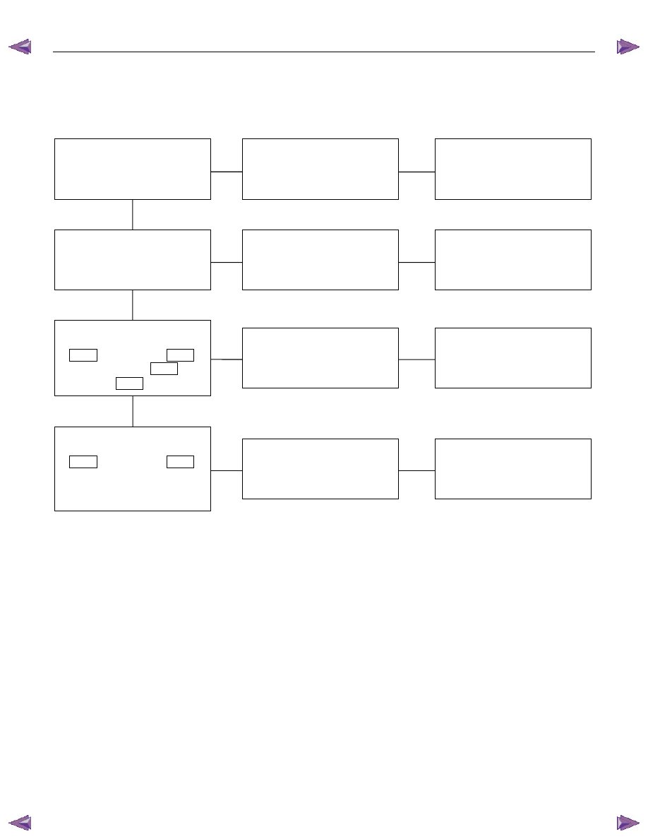
WARNING AND INDICATOR LIGHT
1. When the parking brake lever is pulled, the brake indicator light does not light up
Checkpoint
Trouble
Cause
Countermeasure
Replace or reinstall the bulb
Bulb burned out or loose
contact
NG
Adjust or replace the parking
brake SW.
Parking brake SW. installation
position and function
Incorrect SW. adjustment or
poor SW. point contact
Continuity between the
parking brake SW. connector
1
C39
(stick type), 1
R4
(lever type), and 4
B23
(C24SE : 9
B23
)
Repair open circuit or
connector contact
Open circuit or poor connector
contact
NG
NG
OK
OK
Brake indicator light bulb
continuity
NG
OK
Continuity between the
parking brake SW. connector
1
C39
(stick type), 1
R4
(lever type) and the ground
when the parking brake is
operated
Replace the parking brake
SW.
Parking brake SW.
malfunction
8A-352 ELECTRICAL-BODY AND CHASSIS
2. When the parking brake lever is released, the indicator light does not go off
Checkpoint
Trouble
Cause
Countermeasure
Adjust the SW. installation
position or replace the parking
brake SW.
Incorrect the parking brake
SW. adjustment or parking
brake SW. faulty
NG
Thermo unit malfunction
Replace the brake fluid level
SW., or repair a short circuit
between the parking brake
SW. connector 1
C39
,
1
R4
and 4
B23
(C24SE :
9
B23
) or the brake fluid
level SW. connector 2
C37
and 4
B23
(C24SE : 9
B23
)
Check to see if the indicator
light goes off when the parking
brake SW. connector 1
C39
(stick type), 1
R4
(lever
type) is disconnected
Brake fluid level SW. faulty or
short circuit
NG
OK
Parking brake SW. installation
position and function
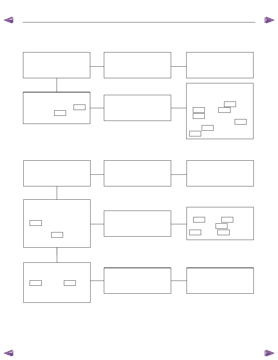
3. Oil pressure warning light does not go off while engine is running
Refer to ENGINE Section
Refer to ENGINE Section
NG
Thermo unit malfunction
Check to see the warning light
goes off when the oil pressure
SW. connector
1
E1
is disconnected or
when the PIM (Oil pressure)
connector 6
B96
(HFV6) is
disconnected
Repair a short circuit between
1
E1
and 39
B23
(C24SE : 17
B24
) or 6
B96
and 39
B23
(HFV6)
Short circuit
NG
OK
Replace the oil pressure SW.
Continuity between the oil
pressure SW. connector
1
E1
(HFV6 : 6
B96
)and
the body ground when the
engine is operating
Oil pressure SW. faulty
NG
OK
Engine oil pressure
ELECTRICAL-BODY AND CHASSIS 8A-353
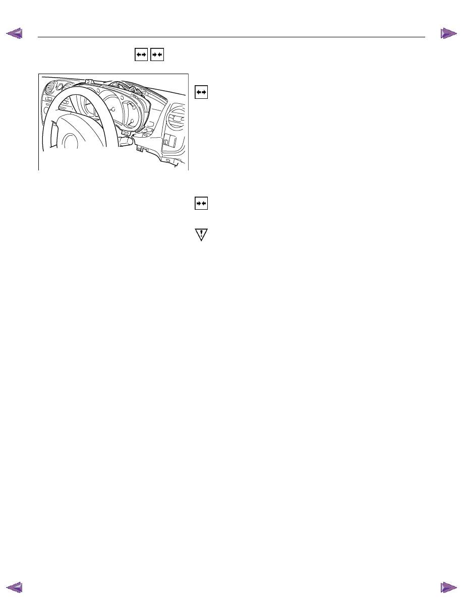
REMOVAL AND INSTALLATION
RTW780SH001701
This illustration is based on RHD model
METER ASSEMBLY
Removal
1. Meter Cluster Assembly
• Refer to the removal steps of “INSTRUMENT PANEL” in
Section 10 “CAB”
2. Meter Assembly
• Remove three screws of the meter assembly.
• Disconnect the meter connectors.
Installation
Follow the removal procedure in the reverse order to install the
meter.
Pay close attention to the important points mentioned in the
following paragraphs.
Connector
Be absolutely sure that the meter connectors are securely
connected.
This will prevent a poor contact and an open circuit.
Wire Harness
Do not pinch the wire harness between the cluster and the
meter hood during the meter assembly installation procedure.
Wire damage will result.
Нет комментариевНе стесняйтесь поделиться с нами вашим ценным мнением.
Текст