Isuzu KB P190. Manual — part 658
Engine Mechanical – V6
Page 6A1–153
8
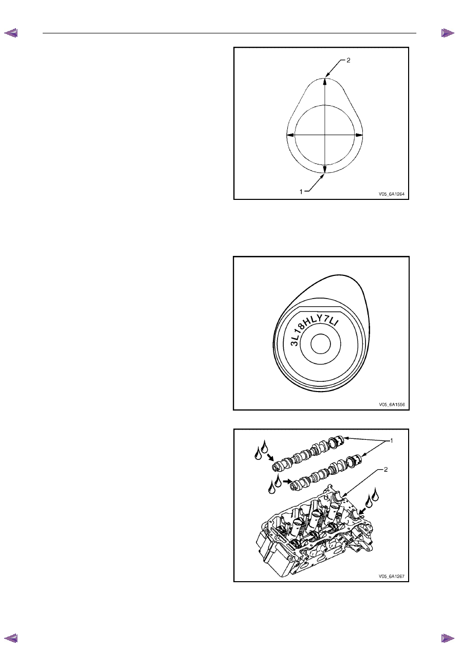
Place the dial indicator tip on the base circle (1) of the
camshaft lobe.
9
Set the dial indicator at zero.
10
Rotate the camshaft until the indicator tip is at the
highest point (2) on the lobe. This reading is the lift of
the camshaft lobe.
Figure 6A1 – 253
Reinstall
Right-hand Side
1
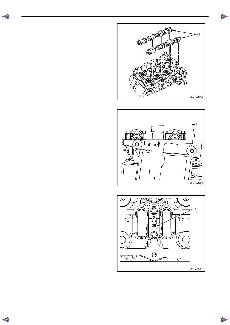
Select the correct camshaft for the particular
installation location. ID markings are on the rear end
of each camshaft. The ID markings are defined as
follows:
•
The first five digits refer to the date and time of
production.
•
Example = 3L18H.
•
Digits six through nine refer to engine
production code.
•
LY7 = Alloytec 190 engine.
•
The last two digits refer to position:
•
LI = left-hand intake.
•
LE = left-hand exhaust.
•
RI = right-hand intake.
•
RE = right-hand exhaust.
Figure 6A1 – 254
2
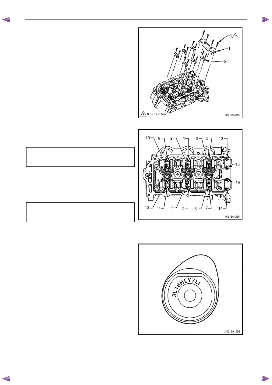
Apply a liberal amount of engine oil to the
camshaft (1) journals and the right-hand cylinder
head camshaft carriers (2).
Figure 6A1 – 255
Engine Mechanical – V6
Page 6A1–154
3
Position the camshafts (1) on the cylinder head and
assemble the camshaft sprockets to the camshafts.
N O T E
Install the camshaft sprocket bolts but do not
tighten at this stage.
Figure 6A1 – 256
4
Ensure the camshaft lobes are in the neutral position
with the flats on the back of the camshafts up and
parallel (1) with the right-hand cylinder head camshaft
cover rail.
5
Ensure the marks on the right-hand exhaust camshaft
position actuator and timing chain, made prior to the
disassemble operation are aligned.
6
Ensure the marks on the right-hand intake camshaft
position actuator and timing chain, made prior to the
disassemble operation are aligned.
Figure 6A1 – 257
7
Observe the markings on the right-hand cylinder head
camshaft bearing caps. Each bearing cap is
marked (1) to identify its location. The markings have
the following meanings:
•
The raised feature must always be oriented
toward the centre of the cylinder head.
•
The I indicates the intake camshaft.
•
The E indicates the exhaust camshaft.
•
The number 1, 3, 5 indicates the cylinder
position from the front of the engine.
8
Apply a liberal amount of engine oil to the camshaft
bearing caps.
Figure 6A1 – 258
Engine Mechanical – V6
Page 6A1–155
9
Install the camshaft bearing thrust cap (1) in the first
journal of the right-hand cylinder head.
10
Install the remaining bearing caps (2) with their
orientation mark toward the centre of the cylinder
head.
11
Hand start all the camshaft bearing cap bolts (3).
Figure 6A1 – 259
12
Tighten the camshaft bearing cap bolts to the correct
torque specification and in the sequence shown.
Camshaft bearing cap attaching
bolt torque specification:
Stage 1:. . . . . . . . . . . . . .8.0 – 12.0 Nm
13
Loosen the centre intake camshaft bearing cap bolts
1 and 2, and the centre exhaust camshaft bearing cap
bolts 3 and 4.
14
Retighten the centre camshaft bearing cap bolts 1, 2,
3 and 4 to the correct torque specification.
Camshaft bearing cap attaching
bolt torque specification:
Stage 2:. . . . . . . . . . . . . .8.0 – 12.0 Nm
Figure 6A1 – 260
Left-hand Side
1
Select the correct camshaft for the particular
installation location. ID markings can be found on the
rear end of each camshaft. The ID markings are
defined as follows:
•
The first five digits refer to the date and time of
production.
•
Example = 3L18H.
•
Digits six through nine refer to engine
production code.
•
LY7 = Alloytec 190 engine.
•
The last two digits refer to position:
•
LI = left-hand intake.
•
LE = left-hand exhaust.
•
RI = right-hand intake.
•
RE = right-hand exhaust.
Figure 6A1 – 261

Engine Mechanical – V6
Page 6A1–156
2
Apply a liberal amount of engine oil to the camshaft
journals and the left-hand cylinder head camshaft
carriers.
Figure 6A1 – 262
3
Position the camshafts (1) on the cylinder head and
assemble the camshaft sprockets to the camshafts.
N O T E
Install the camshaft sprocket bolts but do not
tighten at this stage.
Figure 6A1 – 263
4
Ensure the camshaft lobes are in the neutral position
with the flats on the back of the camshafts up and
parallel (1) with the left-hand cylinder head camshaft
cover rail.
5
Ensure the marks on the left-hand exhaust camshaft
position actuator and timing chain, made prior to the
disassemble operation are aligned.
6
Ensure the marks on the left-hand intake camshaft
position actuator and timing chain, made prior to the
disassemble operation are aligned.
Figure 6A1 – 264
Нет комментариевНе стесняйтесь поделиться с нами вашим ценным мнением.
Текст