Isuzu KB P190. Manual — part 659
Engine Mechanical – V6
Page 6A1–157
7
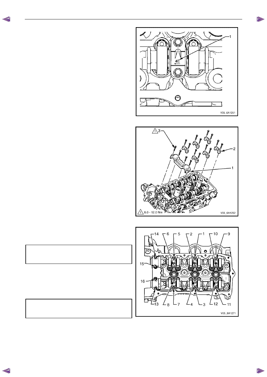
Observe the markings on the left-hand cylinder head
camshaft bearing caps. Each bearing cap is
marked (1) to identify its location. The markings have
the following meanings:
•
The raised feature must always be oriented
toward the centre of the cylinder head.
•
The I indicates the intake camshaft.
•
The E indicates the exhaust camshaft.
•
The number 2, 4, 6 indicates the cylinder
position from the front of the engine.
8
Apply a liberal amount of engine oil to the camshaft
bearing caps.
Figure 6A1 – 265
9
Install the camshaft bearing thrust cap (1) in the first
journal of the left-hand cylinder head.
10
Install the remaining bearing caps (2) with their
orientation mark toward the centre of the cylinder
head.
11
Hand start all the camshaft bearing cap bolts (3).
Figure 6A1 – 266
12
Tighten the camshaft bearing cap bolts to the correct
torque specification and in the sequence shown.
Camshaft bearing cap
bolt torque specification:
Stage 1:. . . . . . . . . . . . . .8.0 – 12.0 Nm
13
Loosen the centre intake camshaft bearing cap bolts
1, and 2, and the centre exhaust camshaft bearing
cap bolts 3 and 4.
14
Retighten the centre camshaft bearing cap bolts 1, 2,
3 and 4 to the correct torque specification.
Camshaft bearing cap
bolt torque specification:
Stage 2:. . . . . . . . . . . . . .8.0 – 12.0 Nm
Figure 6A1 – 267
Engine Mechanical – V6
Page 6A1–158
3.20 Rocker
Arm
Remove
1
Remove the camshafts from the appropriate cylinder head, refer to 3.19
Camshaft.
2
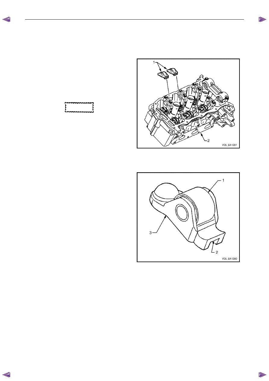
Remove the rocker arm (1) from the cylinder head (2).
N O T E
Record the rocker arm positions during removal.
CAUTION
If the rocker arms are being reused, they
must be reinstalled in their original location.
Figure 6A1 – 268
Clean and Inspect
1
Inspect the rocker arm roller (1) for the following:
•
flat spots,
•
excessive scoring and pitting, and
•
ensure the roller spins freely
2
Inspect the rocker arm valve tip area (2).
3
Inspect the rocker arm stationary hydraulic lash
adjuster (SHLA) pivot area (3).
4
Replace the rocker arm as required.
Figure 6A1 – 269
Engine Mechanical – V6
Page 6A1–159
Reinstall
1
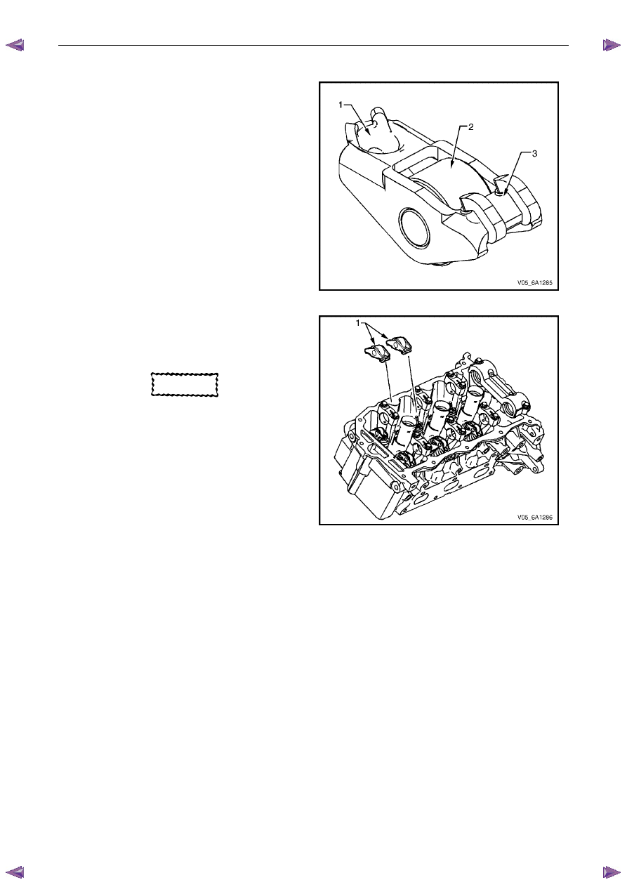
Apply a liberal amount of commercially available
camshaft / lifter prelube or equivalent to the pivot
pocket (1), roller (2) and valve slot (3) areas of the
camshaft followers.
Figure 6A1 – 270
2
Place the rocker arm in position on the valve tip and
stationary hydraulic lash adjuster (SHLA). The
rounded head end of the arm seats on the SHLA
while the flat end seats on the valve tip.
CAUTION
• The rocker arm (1) must be positioned
squarely on the valve tip so the full width
of the roller will completely contact the
camshaft lobe.
• If the rocker arms are being reused, they
must be reinstalled in their original
location.
3
Clean the camshaft journals and carriers with a clean,
lint-free cloth.
4
Reinstall the camshafts, refer to 3.19 Camshaft.
Figure 6A1 – 271
Engine Mechanical – V6
Page 6A1–160
3.21 Stationary Hydraulic Lash Adjuster
Remove
1
Remove the rocker arms from the appropriate
cylinder head, refer to 3.20
Rocker Arm.
2
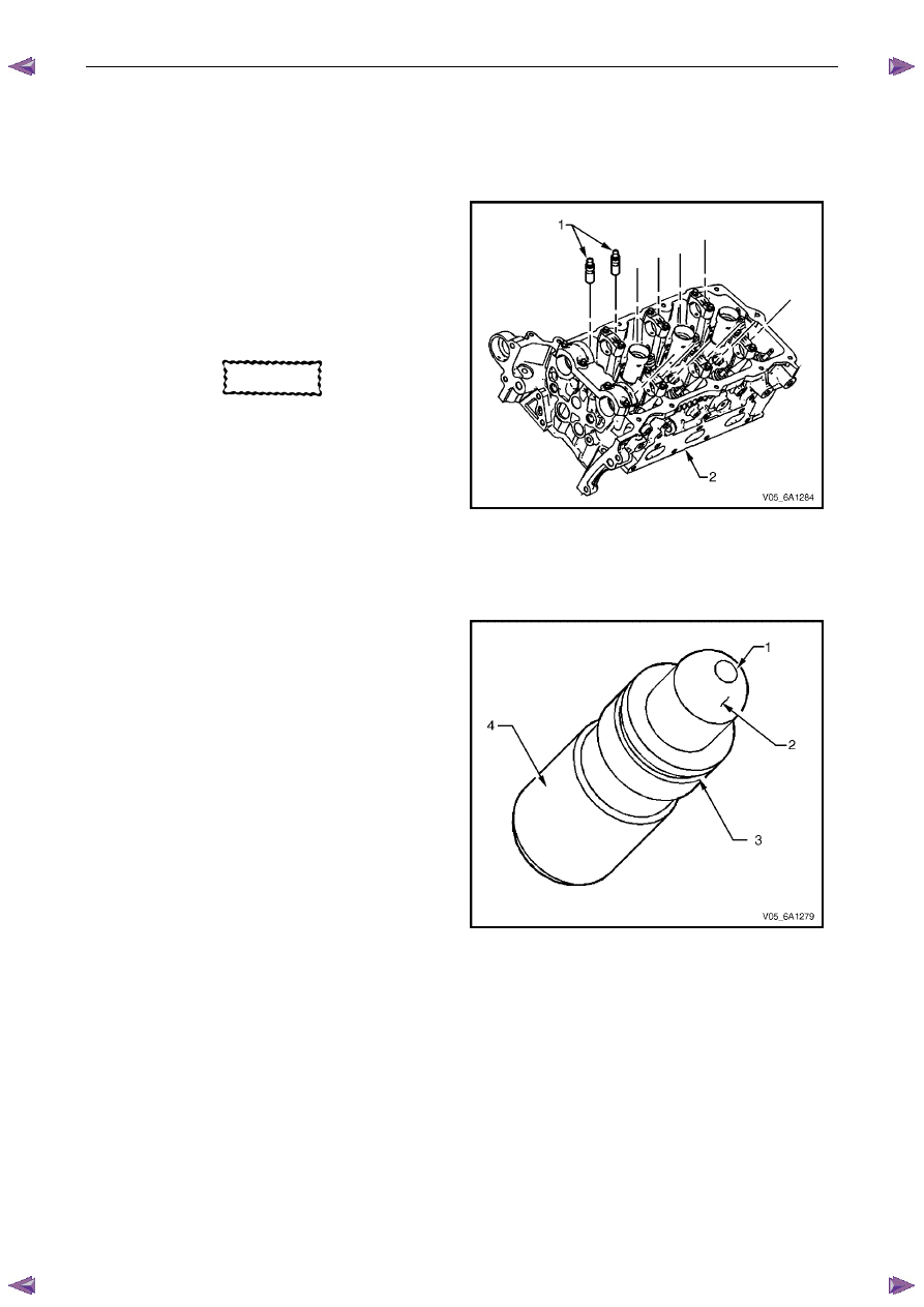
Remove the stationary hydraulic lash adjuster (SHLA)
from the cylinder head (2).
CAUTION
• Do not stroke/cycle the stationary
hydraulic lash adjuster (1) plunger
without oil in the lower pressure
chamber.
• Do not allow the stationary hydraulic lash
adjuster to tip over, plunger down, after
the oil fill.
Figure 6A1 – 272
Clean and Inspect
1
Inspect the stationary hydraulic lash adjuster (SHLA)
in the following areas:
•
a plugged oil passage (1),
•
a scored or worn camshaft follower pivot
area (2),
•
a damaged or broken retainer (3), and
•
a severely scuffed or worn SHLA body (4).
2
Replace the SHLA as required.
Figure 6A1 – 273
Нет комментариевНе стесняйтесь поделиться с нами вашим ценным мнением.
Текст