Isuzu KB P190. Manual — part 664
Engine Mechanical – V6
Page 6A1–177
11
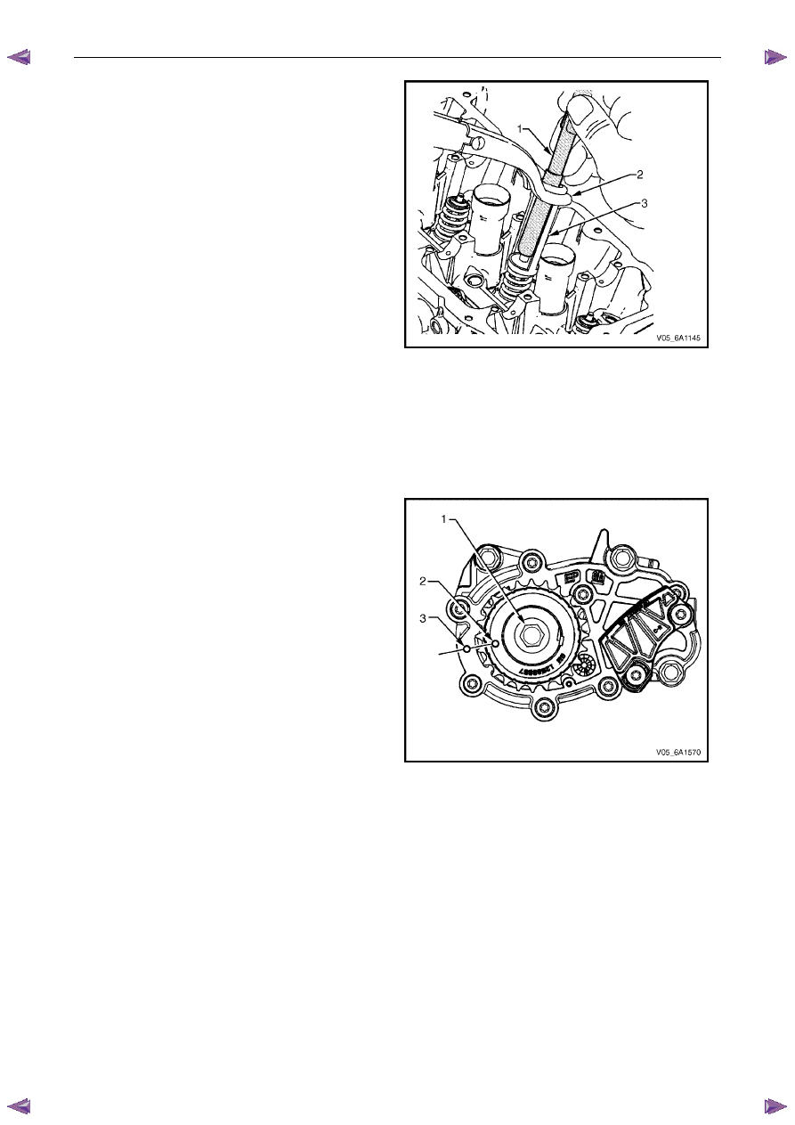
Place the collets into position by pushing the tool (1)
downward and releasing tension on the valve spring
compressor (2).
12
Verify the valve collets are installed by placing a rag
over the valve tip and tapping with a dead-blow
hammer. The valve collets and the spring should
remain in place.
Figure 6A1 – 305
Reinstall
Right-hand Side (Bank 1) Cylinder Head
The reinstallation procedure for the right-hand side cylinder head assembly is the reverse of the removal procedure,
noting the following:
1
Ensure all fasteners are tightened to the correct torque specification.
2
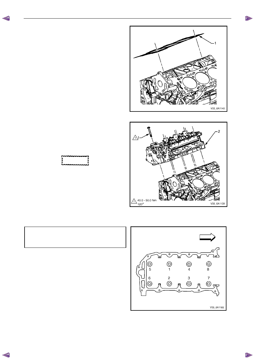
Using crankshaft rotation Tool No. EN-46111 (1),
align the crankshaft sprocket timing mark (2) with the
indexing mark (3) on the oil pump housing.
Figure 6A1 – 306
Engine Mechanical – V6
Page 6A1–178
3
Ensure the deck face is clean and the cylinder head
locating pins are securely mounted in the cylinder
block deck face.
4
Install a new right-hand cylinder head gasket (1)
using the deck face locating pins for retention.
Figure 6A1 – 307
5
Align the cylinder head with the locating pins.
6
Place the cylinder head in position on the deck face.
N O T E
Do not allow oil on the cylinder head bolt
bosses.
CAUTION
Do not reuse the old M11 cylinder head bolts
(1 to 8 inclusive).
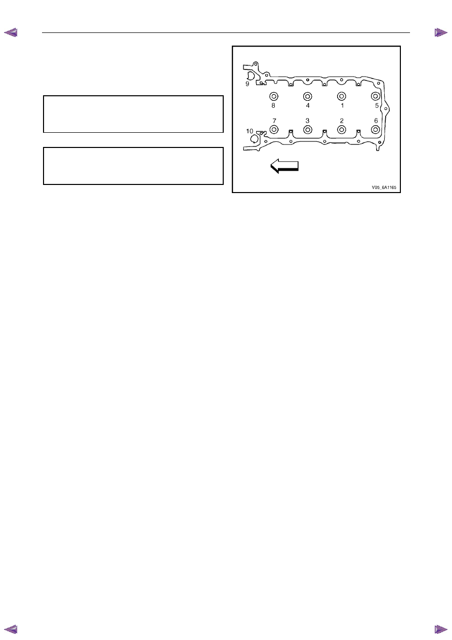
7
Install new M11 cylinder head bolts (1) eight places
and tighten in the sequence shown and to the correct
torque specification.
Figure 6A1 – 308
Cylinder head M11 attaching bolt
torque specification:
Stage 1: . . . .40.0 – 50.0 Nm
Stage
2: . . . . . . . ..120°
Figure 6A1 – 309
Left-hand Side (Bank 2) Cylinder Head
The reinstallation procedure for the left-hand side cylinder head assembly is the reverse of the removal procedure, noting
the following:

Engine Mechanical – V6
Page 6A1–179
1
Ensure all fasteners are tightened to the correct torque specification.
2
Using crankshaft rotation Tool No. EN-46111 (1),
align the crankshaft sprocket timing mark (2) with the
indexing mark (3) on the oil pump housing.
Figure 6A1 – 310
3
Ensure the deck face is clean and the cylinder head
locating pins are securely mounted in the cylinder
block deck face.
4
Install a new cylinder head gasket (1) using the deck
face locating pins for retention.
Figure 6A1 – 311
5
Align the cylinder head with the locating pins.
6
Place the cylinder head in position on the deck face.
N O T E
Do not allow oil on the cylinder head bolt
bosses.
CAUTION
Do not reuse the old M11 cylinder head bolts
(1 to 8 inclusive).
7
Install new M11 cylinder head bolt (1), eight places,
and tighten in the sequence shown and to the correct
torque specification.
Figure 6A1 – 312
Engine Mechanical – V6
Page 6A1–180
8
Install the front M8 cylinder head bolt (2), two places,
and tighten in the sequence (9 and 10) and to the
correct torque.
Cylinder head M11 attaching bolt
torque specification:
Stage 1: . . . .40.0 – 50.0 Nm
Stage
2: . . . . . . . ..120°
M8 cylinder head bolt
torque specification
Stage 1: . . . .12.0 – 18.0 Nm
Stage
2: . . . . . . . . 60°
Figure 6A1 – 313
Нет комментариевНе стесняйтесь поделиться с нами вашим ценным мнением.
Текст