Isuzu KB P190. Manual — part 663
Engine Mechanical – V6
Page 6A1–173
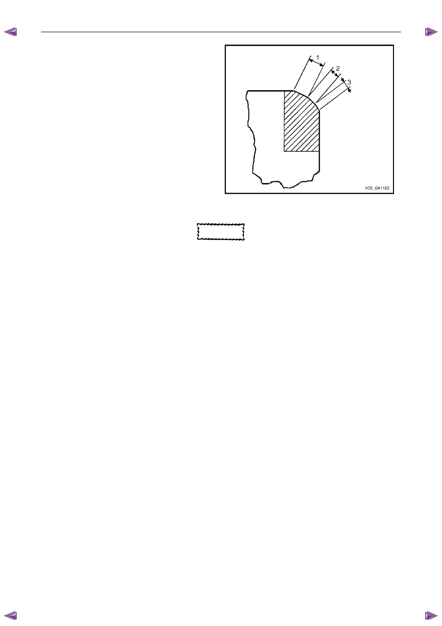
1
Grind the valve seats (2) to the correct angle
specification, refer to 5
Specifications.
2
Using the correct angle specification, grind and
relieve the valve seats (1) to correctly position the
valve seating surface (2) to the valve.
3
Using the correct angle specification, grind and
undercut the valve seats (3) to narrow the valve seat
widths to the specifications, refer to 5 Specifications.
4
If the original valve is being used, grind the valve to
the specifications, refer to 5 Specifications.
Measure the valve margin again after grinding, refer
to Valve Margin Measurement Procedure in this
Section. Replace the valve if the margin is out of
specification. New valves do not require grinding.
5
When grinding the valves and seats, grind off as little
material as possible. Cutting valve seat results in
lowering the valve spring pressure.
6
Install the valve in the cylinder head.
Figure 6A1 – 296
CAUTION
If using refaced valves, lap the valves into the
seats with a fine grinding compound. The
refacing and reseating operations should
leave the refinished surfaces smooth and true
so that minimal lapping is required. Excessive
lapping will groove the valve face and prevent
a good seat when hot.
N O T E
• Clean any remaining lapping compound from
the valve and seat with solvent and
compressed air prior to final assembly.
• If fitting new valves, do not lap the valves
under any condition.
7
After obtaining the correct valve seat width in the cylinder head, measure the valve stem height, refer to Valve
Stem Height Measurement Procedure in this Section.
8
If the valve stem height is acceptable, test the seats for concentricity, refer to Valve-to-Seat Concentricity
Measurement Procedure in this Section.
Engine Mechanical – V6
Page 6A1–174
Valve Stem Height Measurement Procedure
CAUTION
To determine the valve stem height
measurement, measure from the valve
spring seat to the valve spring retainer.
1
Install the valve into the valve guide.
2
Ensure the valve is seated to the valve seat.
3
Install the valve stem oil seal.
4
Install the valve spring retainer and valve stem keys.
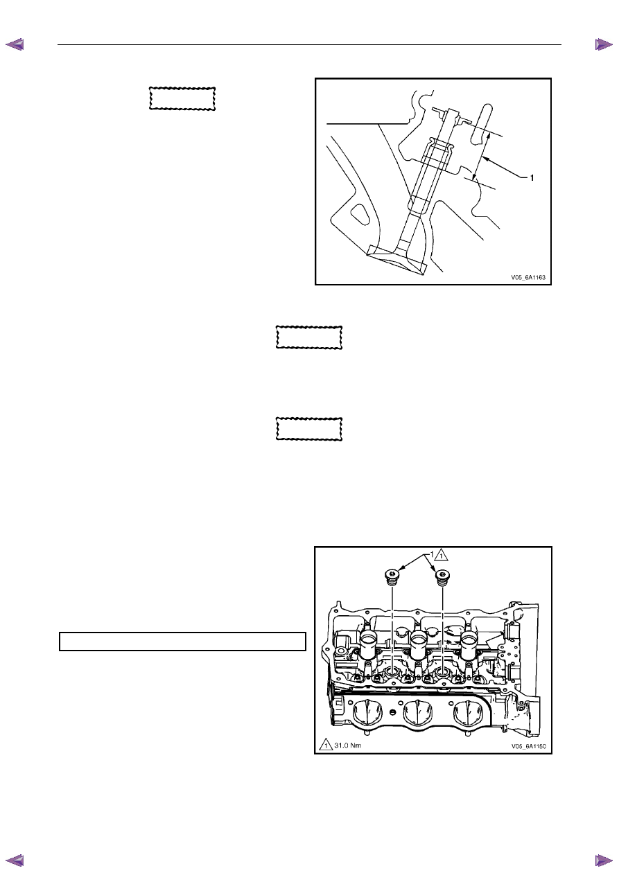
5
Measure the distance (1) between the cylinder head
to the bottom of the valve spring retainer, refer to 5
Specifications.
6
If the maximum height specification is exceeded, a
new valve should be installed and the valve stem
height re-measured.
Figure 6A1 – 297
CAUTION
Do not grind the valve stem tip. The tip of the
valve is hardened and grinding the tip will
eliminate the hardened surface causing
premature wear and possible engine damage.
CAUTION
Do not use shims to adjust valve stem height.
The use of shims will cause the valve spring
to bottom out before the camshaft lobe is at
peak lift and engine damage could result.
7
If the valve stem height still exceeds the maximum height specification, the cylinder head must be replaced.
Assemble
1
Install the cylinder head coolant threaded plugs (1)
and tighten to the correct torque specification.
Cylinder head threaded plug . . . . . . . ..31.0 Nm
Figure 6A1 – 298

Engine Mechanical – V6
Page 6A1–175
2
Install the cylinder head oil gallery expansion
plugs (1).
Figure 6A1 – 299
CAUTION
• Never reuse a valve stem oil seal. Always
use new seals when assembling the
cylinder head.
• Force should only be applied to the valve
spring contact area of the new valve stem
oil seal during installation.
3
Fit the valve stem oil seals onto the guides using Tool
No. EN-46116 (1).
4
Push and twist the valve stem oil seal into position on
the valve guide until the seal positively locks on the
guide using Tool No. EN-46116.
5
Lubricate the valve stem and valve guide ID with
clean engine oil.
Figure 6A1 – 300
CAUTION
The valve stem oil seal must not come loose
from the valve guide when the valve (1) is
installed.
6
Insert the valve into the valve guide until it bottoms on
the valve seat.
Figure 6A1 – 301
Engine Mechanical – V6
Page 6A1–176
7
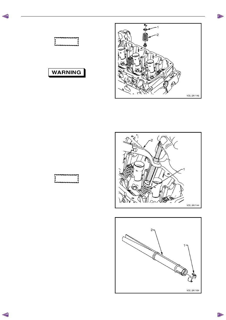
Position the valve spring (2) on the spring seat (1).
8
Place the valve spring retainer onto the valve spring.
CAUTION
Do not compress the valve springs less than
24.0 mm. Contact between the valve spring
retainer and the valve stem oil seal can
cause potential valve stem oil seal damage.
Compressed valve springs (1) have high
tension against the valve spring
compressor (2). Valve springs that are not
correctly compressed by, or are released
from, the valve spring compressor can be
ejected from the valve spring compressor
with intense force. Use care when
compressing or releasing the valve spring
with the valve spring compressor and when
removing or installing the valve stem keys.
Failing to use care may cause personal
injury.
Figure 6A1 – 302
9
Compress the valve spring using valve spring
compressor Tool No. J-8062 and adaptor Tool No.
EN-46119.
CAUTION
Ensure correct directional placement of
valve collets (1) in Tool No. EN-46117 (2).
The valve collets must be installed with the
tapered end towards the valve stem seal.
Figure 6A1 – 303
10
With the spring compressed, install the valve collets
into Tool No. EN 46117.
Figure 6A1 – 304
Нет комментариевНе стесняйтесь поделиться с нами вашим ценным мнением.
Текст