Isuzu KB P190. Manual — part 1124
UNIT REPAIR (JR405E) 7A4-19
Disassembly steps
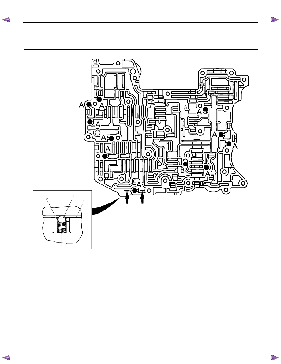
• Remove the 11 steel balls and springs from the control
valve upper body.
244L300005
Legend
1. Steel ball: A – 10 (Silver)
B – 1 (Black)
2.
Spring
3. Separation plate
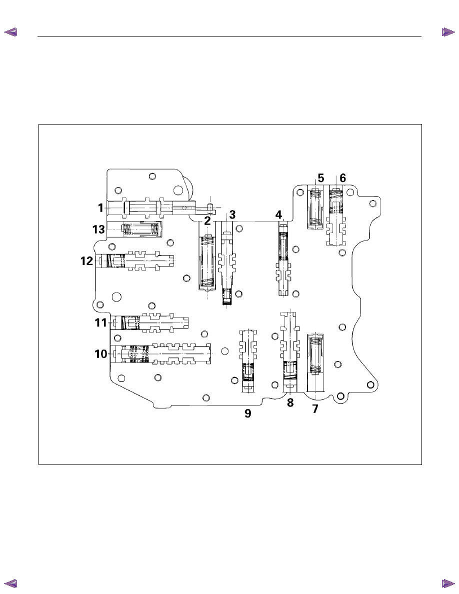
• Remove the control valves from the control valve upper
body.
NOTE:
Place the control valve where it will not get mixed up with
the other parts.
7A4-20 UNIT REPAIR (JR405E)
Inspection
Valve
Inspect each of the valves for denting and other damage.
Spring
Inspect each of the springs for wear and fatigue.
Valve specifications
244L300006
UNIT REPAIR (JR405E) 7A4-21
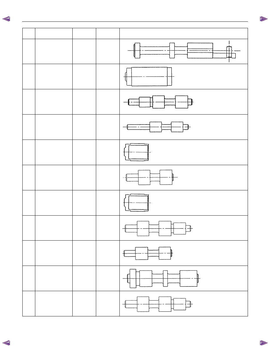
No.
Valve
nomenclature
Diameter
(mm / in)
Length
(mm / in)
Configuration
1 Manual
12.0 /
0.472
82.0 /
3.228
2
2 – 4 brake
accumulator
15.0 /
0.591
37.5 /
1.476
3
Low and reverse
brake fail (B)
10.0 /
0.394
52.0 /
2.047
4 Reverse
stall
8.0 /
0.315
50.0 /
1.969
5
Low and reverse
brake solenoid
accumulator
14.0 /
0.551
19.5 /
0.768
6 Pilot
12.0 /
0.472
38.5 /
1.516
7
Low clutch
solenoid
accumulator
14.0 /
0.551
19.5 /
0.768
8
Low clutch amp
(A)
12.0 /
0.472
53.5 /
2.106
9
2 – 4 brake fail
(B)
10.0 /
0.394
39.0 /
1.535
10 Lock-up
control
12.9 /
0.508
57.5 /
2.264
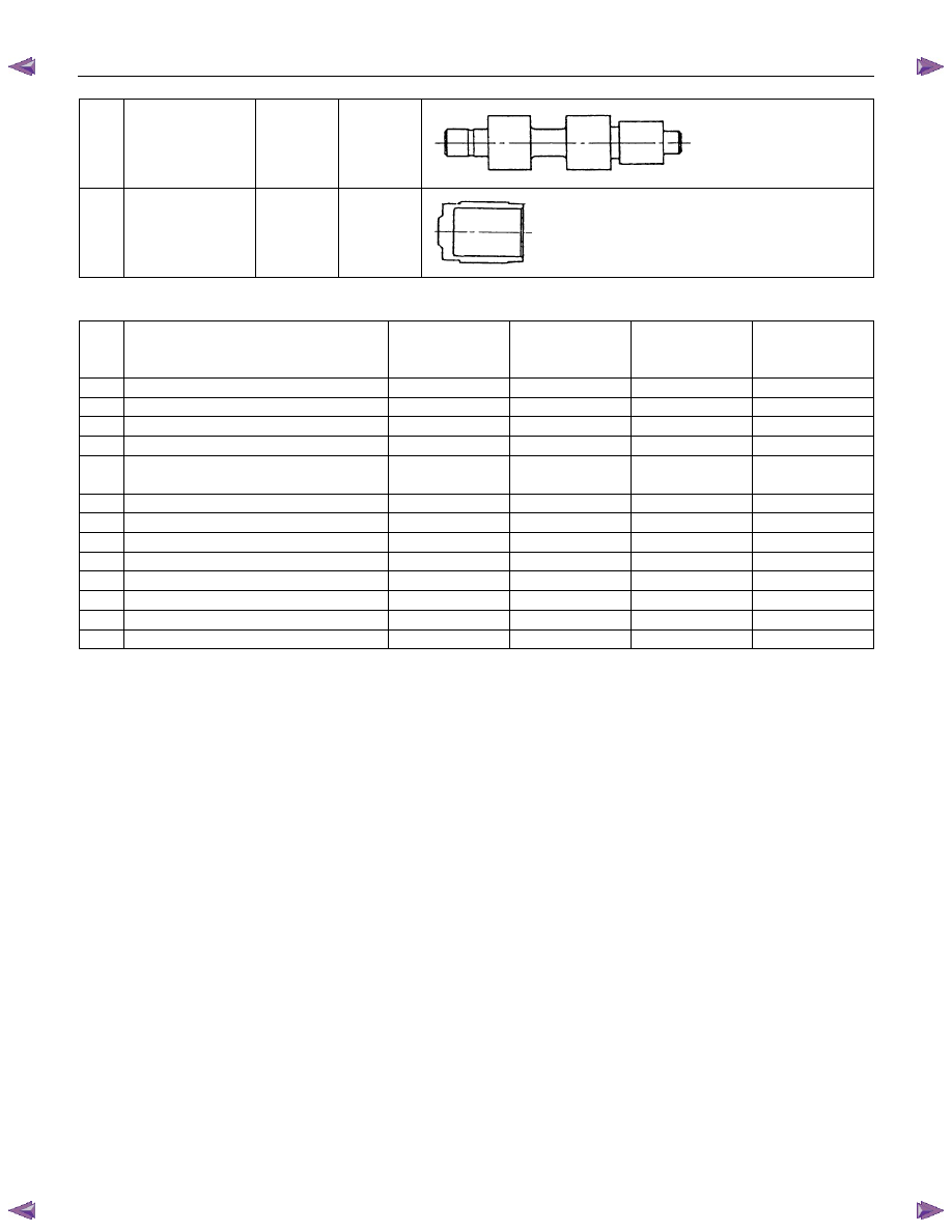
11
2 – 4 brake amp
12.0 /
0.472
53.5 /
2.106
7A4-22 UNIT REPAIR (JR405E)
12
High clutch amp
12.0 /
0.472
53.5 /
2.106
13
High clutch
solenoid
accumulator
14.0 /
0.551
19.5 /
0.768
Spring specifications
No. Valve
nomenclature
Free length
(mm / in)
Outside
diameter (mm
/ in)
Linear
diameter (mm
/ in)
Number of
coils
1 Manual
----
----
----
----
2
2 – 4 brake accumulator
43.9 / 1.728
11.0 / 0.433
2.0 / 0.079
13.1
3
Low and reverse brake fail (B)
22.0 / 0.866
7.0 / 0.276
0.6 / 0.024
10.0
4
Reverse stall
31.5 / 1.240
7.0 / 0.276
1.0 / 0.039
12.8
5 Low and reverse solenoid brake
accumulator
31.4 / 1.236
9.8 / 0.386
1.3 / 0.051
9.3
6
Pilot
32.0 / 1.260
11.0 / 0.433
1.3 / 0.051
9.2
7
Low clutch solenoid accumulator
31.4 / 1.236
9.8 / 0.386
1.3 / 0.051
9.3
8
Low clutch amp (A)
23.0 / 0.906
11.0 / 0.433
0.5 / 0.020
13.2
9
2 – 4 brake fail (B)
24.8 / 0.976
8.5 / 0.335
0.9 / 0.035
7.8
10
Lock-up control
27.0 / 1.063
14.0 / 0.551
1.1 / 0.043
5.7
11
2 – 4 brake amp
23.0 / 0.906
11.0 / 0.433
0.5 / 0.020
13.2
12
High clutch amp
23.0 / 0.906
11.0 / 0.433
0.5 / 0.020
13.2
13
High clutch solenoid accumulator
31.4 / 1.236
9.8 / 0.386
1.3 / 0.051
9.3
Reassembly steps
• Coat the parts with ATF before installing them.
• Install the control valve to the upper body.
• Install the 11 steel balls and springs to the upper body.
Нет комментариевНе стесняйтесь поделиться с нами вашим ценным мнением.
Текст