Isuzu KB P190. Manual — part 1123
UNIT REPAIR (JR405E) 7A4-15
244L300003
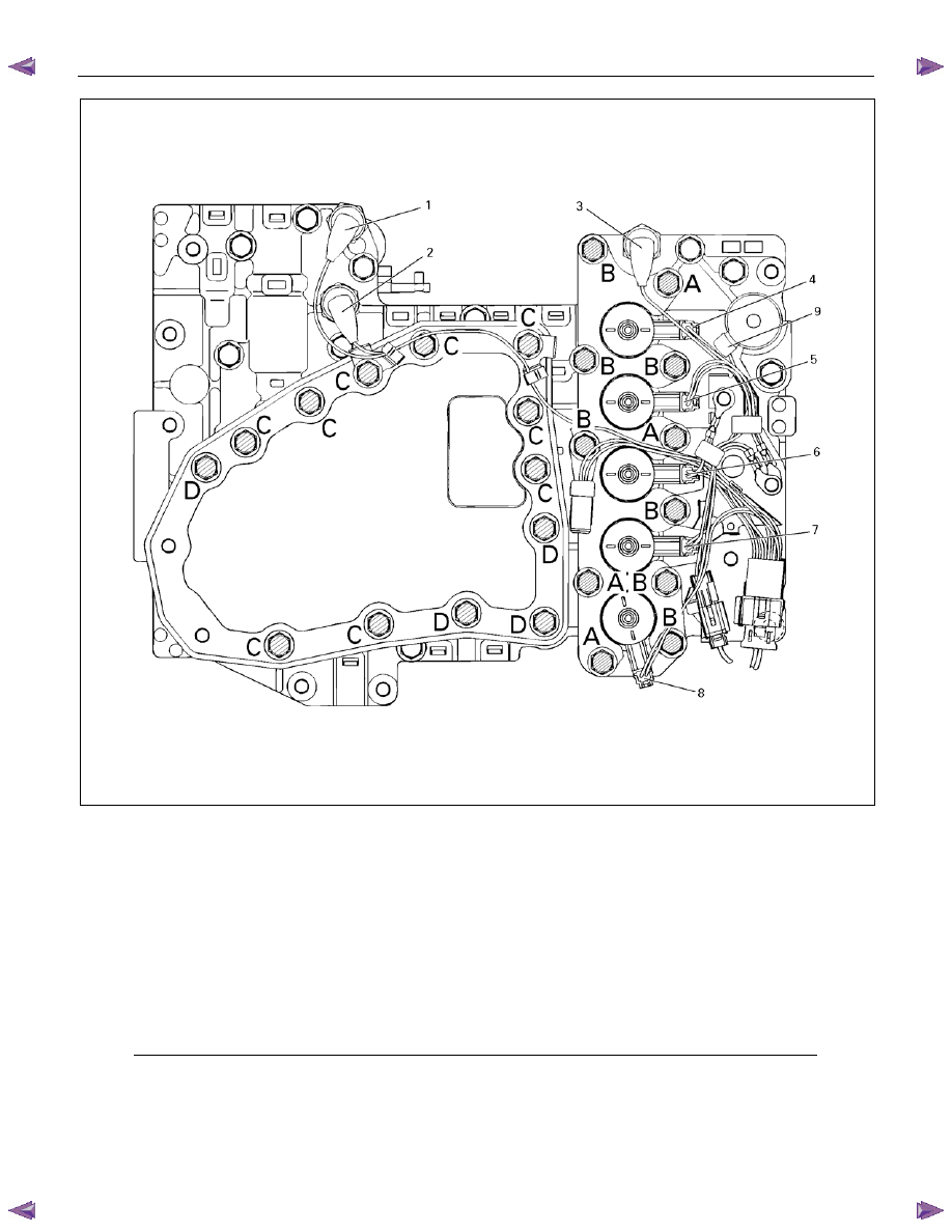
Legend
1. High clutch oil pressure switch connector
(wire color: Gray)
2. 2-4 brake oil pressure switch connector
(wire color: Brown)
3. Low and reverse brake oil pressure
switch connector (wire color: White)
4. Low and reverse brake duty solenoid
connector (wire color: Pink and White)
5. High clutch duty solenoid connector
(wire color: Green and Gray)
6. Lock-up duty solenoid connector (wire
color: Yellow and Black)
7. 2-4 brake duty solenoid connector (wire
color: Blue and Brown)
8. Low clutch duty solenoid connector (wire
color: Orange and Black)
9. Line pressure solenoid connector (wire
color: Pink)
7A4-16 UNIT REPAIR (JR405E)
12CV19
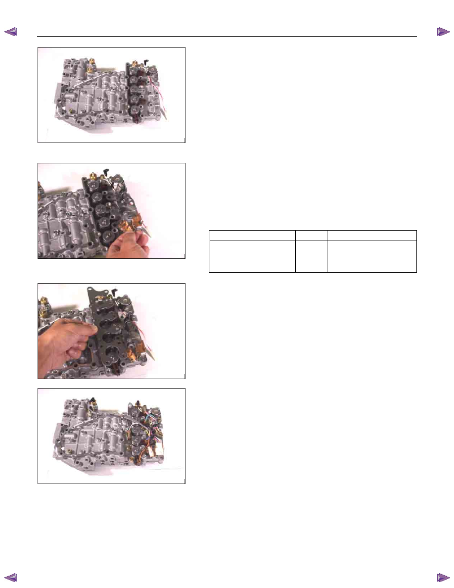
4. Solenoid
5. Oil pressure switch
• Install the O-rings to each of the solenoids.
• Install the 6 solenoids together and the 3 oil pressure
switches.
NOTE:
Be sure the high clutch oil pressure switch is marked.
• Tighten the bolts to the specified torque.
Torque:
Oil pressure switch bolts – 4 N
⋅⋅⋅⋅m (0.4 kgf⋅⋅⋅⋅m/35 Ib⋅⋅⋅⋅in)
Line pressure solenoid bolt (Single gold-colored bolt 16
mm) – 8 N
⋅⋅⋅⋅m (0.8 kgf⋅⋅⋅⋅m/69 Ib⋅⋅⋅⋅in)
6. Solenoid fixing plate
7. Harness bracket
Install the solenoid fixing plate together with the harness
bracket.
Tighten the bolts to the specified torque.
Torque: 8 N
⋅⋅⋅⋅m (0.8 kgf⋅⋅⋅⋅m/69 Ib⋅⋅⋅⋅in)
Number
Length
(Color)
Solenoid fixing plate bolt
(A)
4
16 mm (0.63 in) (Gold)
(B)
7
45 mm (1.77 in) (Silver)
13CV20
14CV21
15CV26
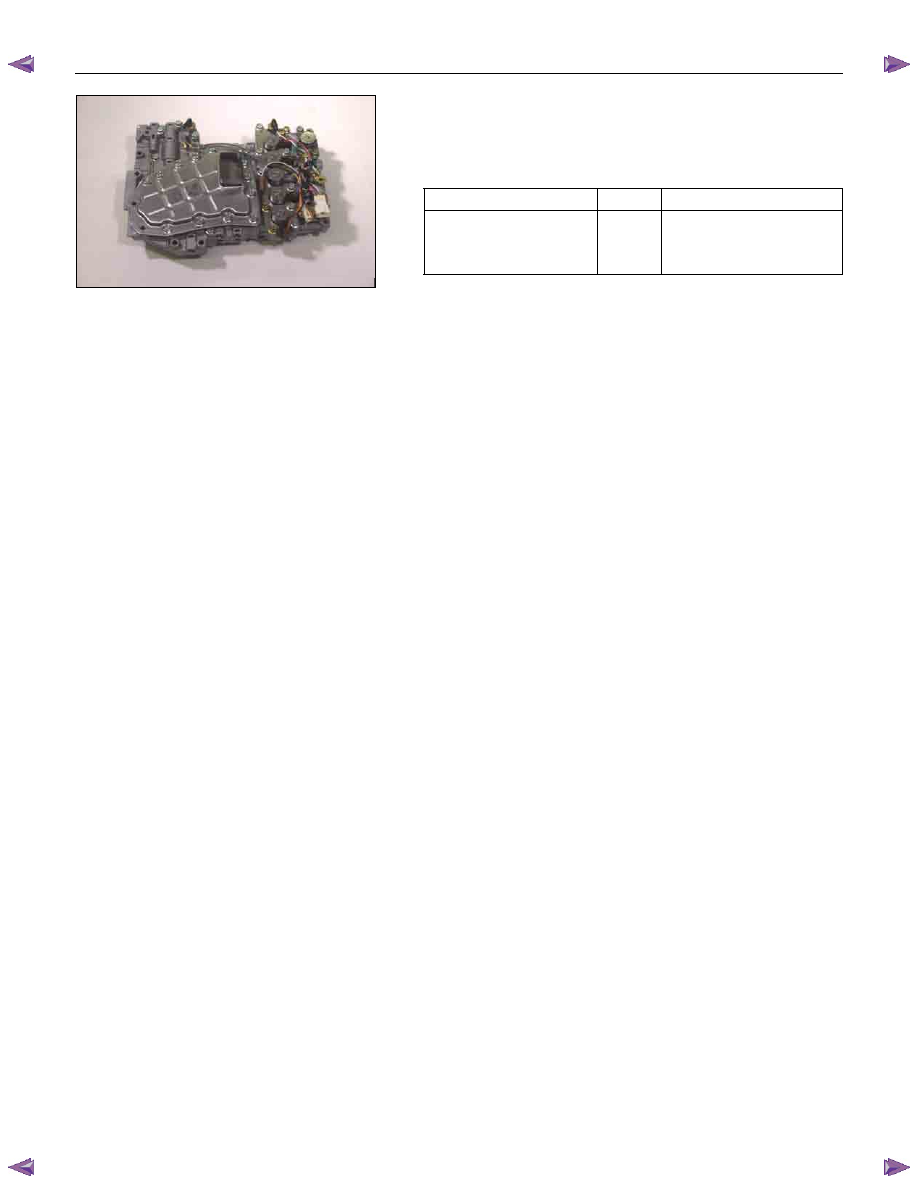
8. Harness assembly
Install the harness assembly.
UNIT REPAIR (JR405E) 7A4-17
9. Oil strainer
Install the oil strainer.
Tighten the bolts to the specified torque.
Torque: 8 N
⋅⋅⋅⋅m (0.8 kgf⋅⋅⋅⋅m/69 Ib⋅⋅⋅⋅in)
Number
Length
(Color)
Oil strainer bolt
(C)
9
13 mm (0.51 in) (Silver)
(D)
4
45 mm (1.77 in) (Silver)
16CV40
7A4-18 UNIT REPAIR (JR405E)
CONTROL VALVE UPPER BODY
09CV02
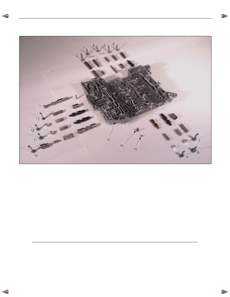
Legend
1. Manual valve, and pin
2. Retainer plate, spring, and 2-4 brake
accumulator
3. Retainer plate, plug, and low and
reverse brake fail valve B
4. Retainer plate, plug, spring, and reverse
stall valve
5. Retainer plate, spring, and low and
reverse brake solenoid accumulator
6. Retainer plate, spring, and pilot valve
7. Retainer plate, spring, and low clutch
solenoid accumulator
8. Retainer plate, plug, spring, and low
clutch amp valve A
9. Retainer plate, plug, spring, and 2-4
brake fail valve B
10. Retainer plate, sleeve, plug, spring, and
lock-up control valve
11. Retainer plate, plug, spring, and 2-4
brake amp valve
12. Retainer plate, plug, spring, and high
clutch amp valve
13. Retainer plate, spring, and high clutch
solenoid accumulator
14. Control valve upper body
15.
Spring
16. Steel ball
Нет комментариевНе стесняйтесь поделиться с нами вашим ценным мнением.
Текст