Isuzu KB P190. Manual — part 229
ENGINE MECHANICAL 6A – 111
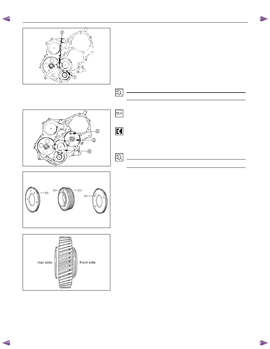
4. Align the idler gear setting mark with the crankshaft
timing gear (1) setting mark.
5. Align the idler gear setting mark with the camshaft
timing gear (2) setting mark.
6. Install the thrust collar and bolts to the cylinder body
through the shaft.
The thrust collar oil hole must be facing up, and the
thrust collar chamfered must be outward.
7. Tighten the idler gear bolt to the specified torque.
Idler Gear "A" Bolt Torque
N·m(kg·m/lbft)
30 (3.1/22)
020R300006
22. Idler Gear "B" and Shaft
1. Apply engine oil to the idler gear and the idler gear shaft.
2. Align the idler gear "B" (3) setting mark with the idler
gear "A" (4) setting mark.
3. Tighten the idler gear bolt to the specified torque.
4. Be sure to remove the lock bolt (5) from idle gear “B”.
Idler Gear "B" Bolt Torque
N·m(kg·m/lbft)
76 (7.7/56)
020L200019
5. If the idle gear "B" is disassembled, reassemble in the
following procedure.
1) Drive pins into the main gear, the front gear, and the
rear gear.
020L200007
2) Install the main gear bearing from the front side of
the main gear (the side with the groove).
3) Place the main gear in a vise with copper plate so
that the rear side of the main gear facing up.
020RY00036
6A – 112 ENGINE MECHANICAL
RTW31BSH000101
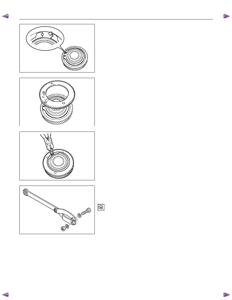
4) Set the spring as shown in the illustration.
RTW31BSH000201
5) Position the rear gear so that the pin is aligned with
the receiving end of the spring.
RTW31BSH000301
6) Install the snap ring to the main gear groove.
RTW31BSH000501
7) Install suitable bolts, nuts and washers to special tool
as shown in the illustration to rotate the scissors
gear.
End yoke holder: 5-8840-2447-0
ENGINE MECHANICAL 6A – 113
RTW31BSH000401
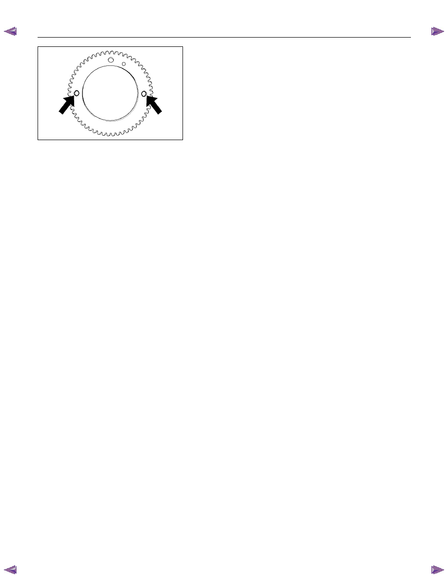
8) Insert the bolts of the special tool into the rear gear
setting hole. Rotate the rear gear to mesh the teeth
of main gear and rear gear.
9) Insert a lock bolt (M6
× 1 L=30) into scissors gear
fixing hole to prevent the scissors gear from turning.
10) Place the main gear in a vise with copper plate so
that the front side of the main gear facing up.
11) Repeat steps 4 to 8 to install the front gear.
12) Lock the front gear, the main gear, and the rear gear
with lock bolt (inserted at Step 8).
6A – 114 ENGINE MECHANICAL
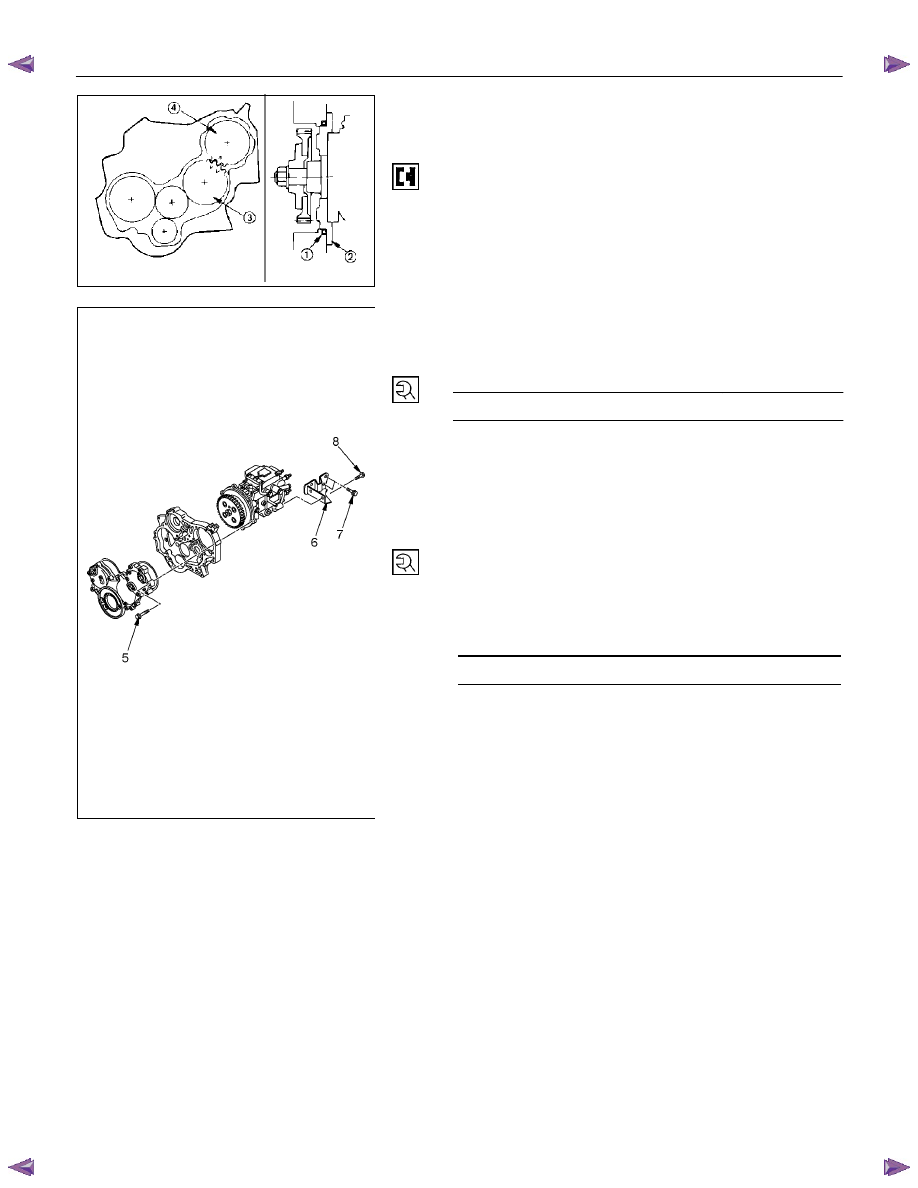
23. Injection Pump
1. Install the O-ring (1) to the injection pump flange (2).
2. Attach the noise insulator rubber to the cylinder body .
3. Install the injection pump to the timing gear case.Align
the idler gear "B" (3) mark with the injection pump timing
gear (4) mark.
RTW36AMH000101
4JA1TC/4JH1TC:
4. Tighten the injection pump bolts (5) to the specified
torque.
Injection Pump Bolt Torque
N·m(kg·m/lbft)
19 (1.9/14)
5. Install the injection pump bracket (6) and the bracket
bolts (7) and (8) to the cylinder body.
Temporarily tighten the bracket bolts.
6. Tighten the bracket bolts (7) to the specified torque.
7. Tighten the bracket bolt (8) to the specified torque.
NOTE:
Tighten the bracket bolt (7) first.
Injection Pump Bracket Bolt Torque
N·m(kg·m/lbft)
19 (1.9/14)
020RY00039
Нет комментариевНе стесняйтесь поделиться с нами вашим ценным мнением.
Текст