Isuzu KB P190. Manual — part 230
ENGINE MECHANICAL 6A – 115
RTW46ASH002201
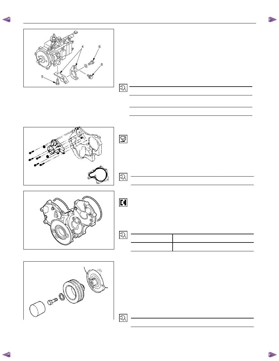
4JA1T(L):
4. Tighten the injection pump bolts to the specified torque.
5. Install the injection pump bracket (4) and the bracket
bolts (5) and (6) to the cylinder body. Temporarily tighten
the bracket bolts.
6. Tighten the bracket bolts (5) to the specified torque.
7. Tighten the bracket bolts (6) to the specified torque.
Injection pump Bracket Bolt Torque (6)
N·m(kg·m/lbft)
19 (1.9/14)
Injection pump Bracket Bolt Torque (5)
N·m(kg·m/lbft)
40 (4.1/30)
030RY00007
24. Water Pump
1. Apply the recommended liquid gasket or its equivalent
to the water pump at the position shown in the
illustration.
Do not apply an excessive amount of liquid gasket.
2. Tighten the water pump bolts to the specified torque.
Water Pump Bolt Torque
N·m(kg·m/lbft)
20 (2.0/14)
25.Timing Gear Case Cover
1. Align the gear case with the timing gear case knock pin
and then install the timing gear case cover.
2. Tighten the gear case cover bolts to the specified
torque.
Gear Case Cover Bolt Torque
N·m(kg·m/lbft)
M8 19
(1.9/14)
M12 76
(7.7/56)
26. Crankshaft Damper Pulley
Tighten the crankshaft damper pulley bolt to the specified
torque.
Note:
Hold the flywheel ring gear stationary to prevent the
crankshaft from turning when tightening the damper
pulley bolt.
Crankshaft Damper Pulley Bolt Torque
N·m(kg·m/lbft)
206 (21/152)
Take care not to damage the crankshaft damper pulley
boss.
014R100014
020R300004
6A – 116 ENGINE MECHANICAL
27. Cylinder Head Gasket
The cylinder head gasket "TOP" mark must be facing up.
NOTE:
Before the gasket installation, measure the piston
head projection and select the appropriate head
gasket.
Refer to "INSPECTION AND REPAIR", "Cylinder Head
Gasket Selection".
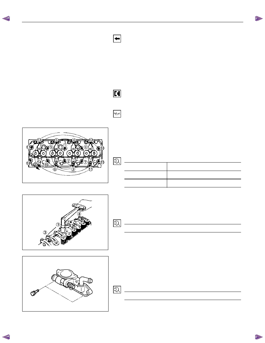
28. Cylinder Head
1. Align the cylinder body dowels and the cylinder head
dowel holes.
Carefully place the cylinder head on the cylinder head
gasket.
2. Apply a coat of engine oil to the cylinder head bolt
threads and setting faces.
3. Tighten the cylinder head bolts in three steps of anglar
tightening methed.
Follow the numerical sequence shown in the
illustration.
Cylinder Head Bolt Torque
N·m(kg·m/lbft)
1st step
49 (5.0/36)
2nd step
60
° - 75°
3rd step
60
° - 75°
30. Rocker Arm Shaft and Rocker Arm
Tighten the rocker arm shaft bracket bolts in the numerical
order shown in the illustration.
Rocker Arm Shaft Braket Bolt Torque
N·m(kg·m/lbft)
54 (5.5/40)
31. Thermostat Housing
1. Install the thermostat housing.
2. Tighten the thermostat housing bolts to the specified
torque.
Thermostat Housing Bolt Torque
N·m(kg·m/lbft)
19 (1.9/14)
014LX083
011LX073
031R300002
ENGINE MECHANICAL 6A – 117
RTW46ASH001201
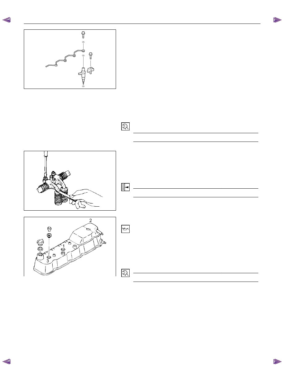
33. Injection Nozzle Holder
1. Install the injection nozzle gasket and the O-ring to the
injection nozzle holder.
Be sure that the O-ring fits snugly in the injection
nozzle groove.
2. Install the nozzle holder toghther with the nozzle holder
bracket to the cylinder head.
3. Tighten the nozzle holder bracket bolt to the specified
torque.
Injection Nozzle Holder Bracket Bolt
Torque
N·m(kg·m/lbft)
37 (3.8/28)
Note on Valve Clearance Adjustment
Valve clearances must be adjusted before the cylinder
head cover is reinstalled.Refer to "Valve Clearance
Adjustment" in the "Servicing" Section of this manual.
Valve Clearance (At Cold)
mm(in)
0.4 (0.0157)
RTW46ASH001101
34. Cylinder Head Cover
1. Apply engine oil to the rocker arm and the valve spring.
2. Install the cylinder head cover gasket to the head
cover. Check to see that the head cover gasket has no
loose areas.
3. Tighten the cylinder head cover nuts in the numerical
order shown in the illustration.
Cylinder Head Cover Bolt Torque
N·m(kg·m/lbft)
13 (1.3/9.4)
4. Connect the positive crankcase ventilation (PCV) hose
to the cylinder head cover.
014RY00015
6A – 118 ENGINE MECHANICAL
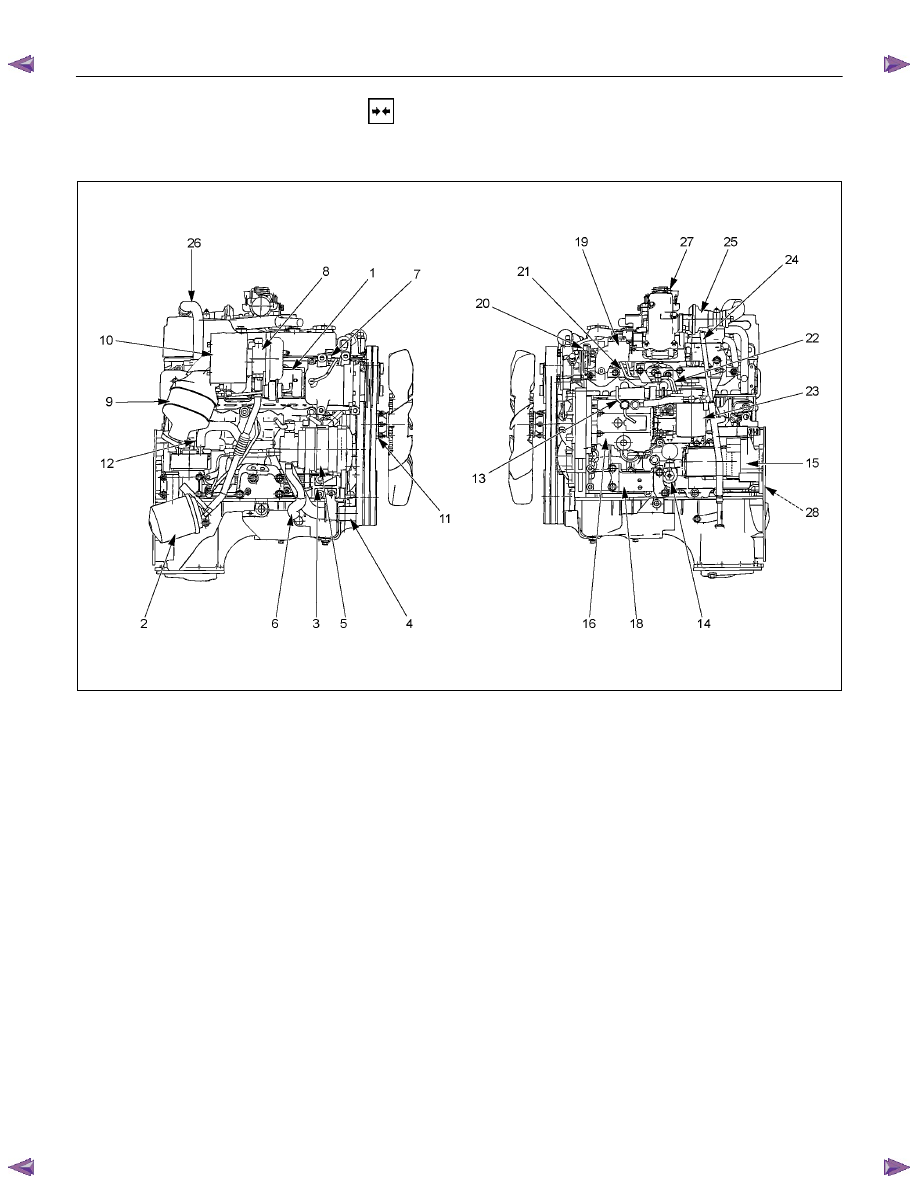
INSTALLATION
EXTERNAL PARTS
RTW36AMF000701
Installation Steps
1.
Exhaust Manifold
18.
Engine Mounting Bracket and
2.
Oil Cooler with Oil Filter
Foot
3.
Generator Bracket
19.
Intake Manifold
4.
Water Inlet Pipe
20.
Power Steering Oil Pump
5.
Generator and Adjusting Plate
Bracket
6.
Vacuum Pump Oil Return Hose
21.
Fuel Injection Pipe with Clip
7.
Compressor Bracket
22.
Fuel Filter Bracket (Except
EURO III)
8. Turbocharger
23.
Fuel Filter Assembly (Except
EURO III)
9.
Catalytic Converter
24.
Oil Level Gauge
10.
Heat
Protector
25.
EGR
Valve
11.
Cooling Fan Pulley
26-1.
EGR Pipe
12.
Oil Cooler Water Pipe
26-2.
EGR Cooler (EURO III model
only)
13.
Fuel Leak Off Pipe
27.
Intake Pipe and Throttle Body
(4JA1TC/4JH1TC only)
14.
Oil Pressure Warning Switch
28.
Clutch Assembly or Flex Plate
15. Starter
Motor
16. Injection
Pump
17.
Injection Pump Cover
Нет комментариевНе стесняйтесь поделиться с нами вашим ценным мнением.
Текст