Isuzu KB P190. Manual — part 228
ENGINE MECHANICAL 6A – 107
RTW36ASH002001
11. Piston and Connecting Rod with Upper Bearing
12. Connecting Rod Bearing Cap with Lower Bearing
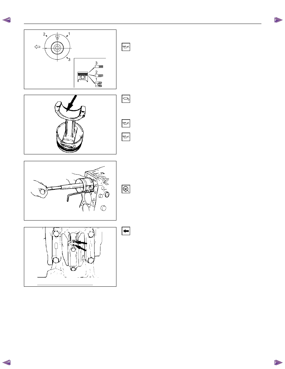
1. Apply a coat of engine oil to the circumference of each
piston ring and piston.
2. Position the piston ring gaps as shown in the
illustration.
1. Oil
ring
2. 2nd compression ring
3. 1st compression ring
3. Apply a coat of molybdenum disulfide grease to the two
piston skirts.
This will facilitate smooth break-in when the engine is
first started after reassembly.
4. Apply a coat of engine oil to the upper bearing
surfaces.
5. Apply a coat of engine oil to the cylinder wall.
6. Position the piston head front mark so that it is facing
the front of the engine.
7. Use the piston ring compressor to compress the piston
rings.
Piston Ring Compressor: 5-8840-9018-0
8. Use a hammer grip to push the piston in until the
connecting rod makes contact with the crankpin.
At the same time, rotate the crankshaft until the
crankpin is at BDC.
9. Align the bearing cap cylinder number marks and the
connecting rod cylinder number marks.
The cylinder number marks must be turned toward the
exhaust manifold.
015LX096
015R100007
015R100006
6A – 108 ENGINE MECHANICAL
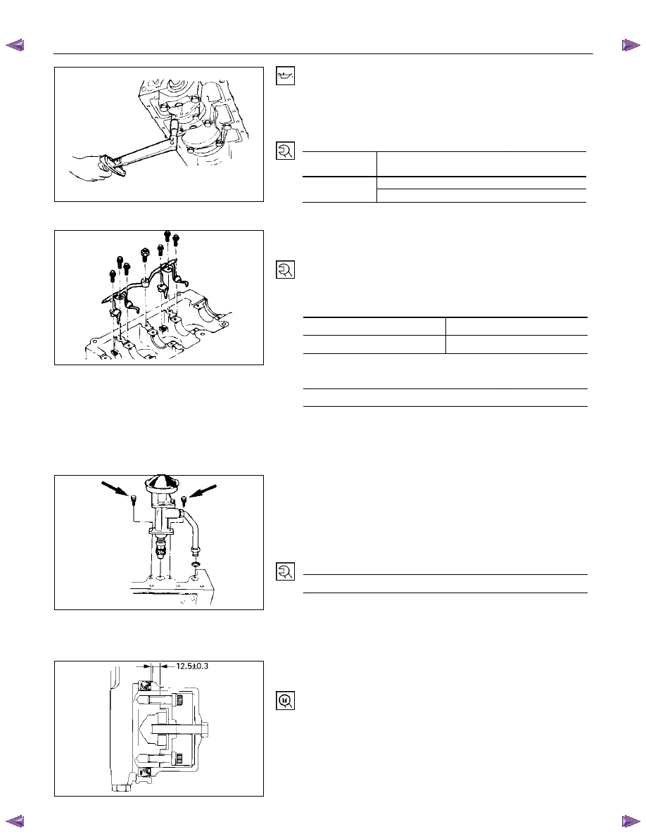
10. Apply a coat of engine oil to the threads and setting
faces of each connecting rod cap bolt.
11. Tighten the connecting rod caps to the two step of
anglar tigthen method.
Connecting Rod Bearing Cap Bolt Torque
N·m (kg·m/Ib ft)
4JA1T (L),
4JA1TC
78-88 (8.0/57 – 9.0/65)
1st step; 29.0–29.2 (3.00/22.0–3.01/22.2)
4JH1TC
2nd step; 45
°-60°
13. Piston Cooling Oil Jet
1. Install the piston cooling oil jet to the cylinder body.
2. Tighten the oil jet bolts and relief valve to the specified
torque.
Oil Jet Bolt Torque
N·m(kg·m/lb ft)
M8
× 1.25
19 (1.9/14)
M6
× 1.00
8 (0.8/6)
Relief Valve Torque
N·m(kg·m/lb ft)
29 (3.0/22)
NOTE:
Check that there is no interference between the piston
and the oiling jet by slowly rotating the crankshaft.
14. Oil Pump with Oil Pipe
Apply a coat of the molybdenum disul fide and engine oil
enough on the pinion gear.
Install the oil pump with the oil pipe and tighten the bolts to
the specified torque.
Oil Pump Bolt Torque
N·m(kg·m/lb ft)
19 (19/14)
NOTE:
Take care not to damage the O-rings when tightening
the oil pipe bolts.
15. Crankshaft Rear Oil Seal
Use a oil seal install to install the crankshaft rear oil seal.
Oil Seal Installer: 5-8840-2359-0
015LX130
015LX112
052LX010
051R100004

ENGINE MECHANICAL 6A – 109
16. Crank Case
1. Apply the recommended liquid gasket (Three bond
1207B) or its equivalent to arch gasket fitting surface
as shown in the illustration.
2. Install the crankcase front gasket (1) to the timing gear
case arches.
The gasket projection (2) must be facing forward.
NOTE:
ThreeBond 1207B is a fast-drying liquid gasket.
Install the arch packing to the crankcase immediately
aftter applying the gasket.
3. Install the rear arch gasket (2) to the No. 5 bearing
cap. Use your fingers to push the arch gasket into the
bearing cap groove.Take care not to scratch the arch
gasket outer surface.
Also apply the recommended liquid gasket (1207C) or
its equivalent to arch gasket fitting area as indicated in
the illustration.
4. Apply the recommended liquid gasket or its equivalent
to groove of the crankcase fitting surface as shown in
the illustration.
NOTE:
Be sure that the crank case fitting surface is
completely free of oil and dust before applying the
liquid gasket.
5. Install the crank case to the cylinder body.
6. Tighten the crank case bolts to the specified torque a
little at a time in the sequence shown in the illustration.
Crank Case Bolt Torque
N·m(kg·m/lbft)
19 (1.9/14)
013LV003
013RW012
013RW011
013R100001
6A – 110 ENGINE MECHANICAL
17. Cylinder Body Rear Plate
1. Align the rear plate with the cylinder body knock pins.
2. Tighten the rear plate to the specified torque.
Rear Plate Torque
N·m(kg·m/lbft)
82 (8.4/61)
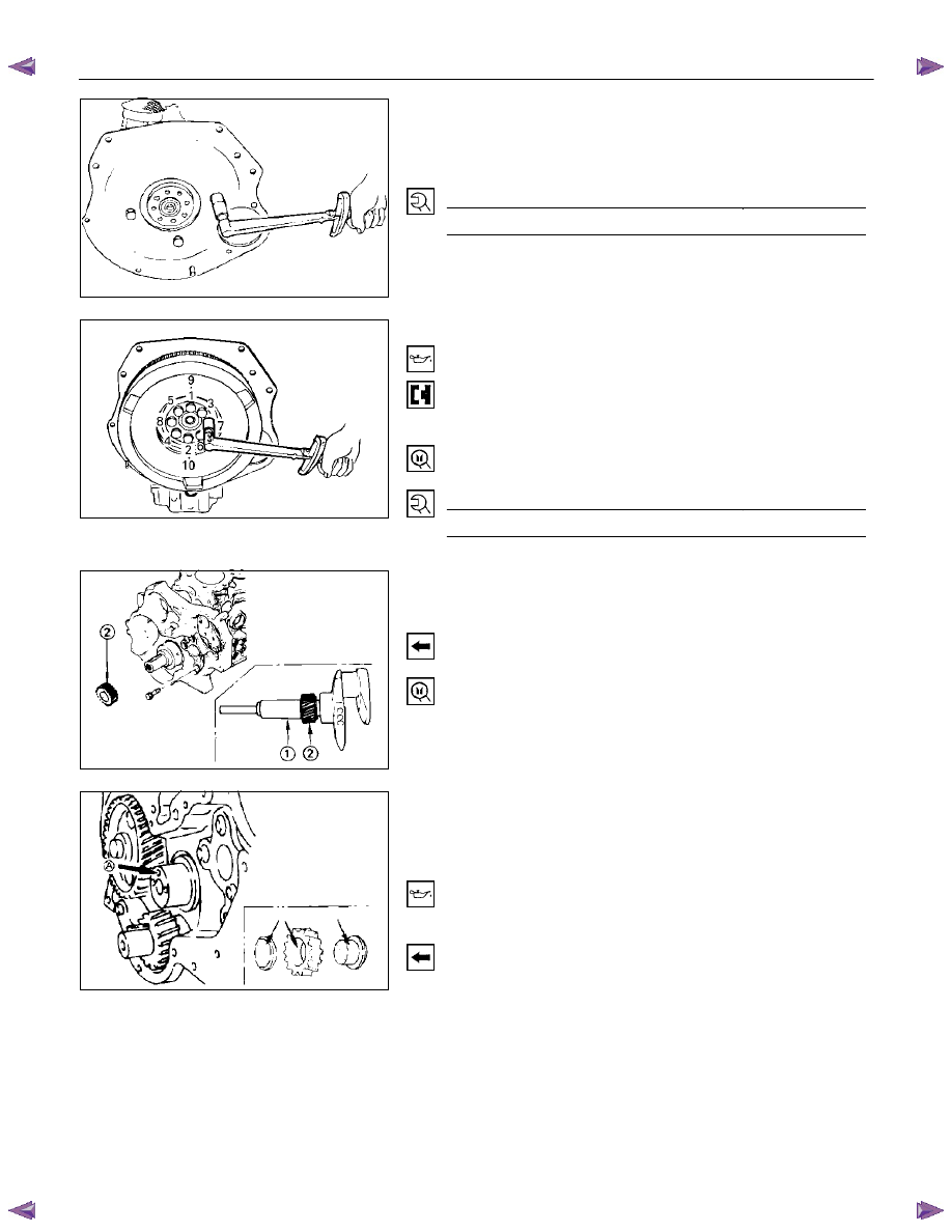
18. Flywheel
1. Apply a coat of engine oil to the threads of the flywheel
bolts.
2. Align the flywheel with the crankshaft dowel pin.
3. Tighten the flywheel bolts in the numerical order shown
in the illustration.
Gear stoper: 5-8840-0214-0
Flywheel Bolt Torque
N·m(kg·m/lbft)
118 (12/87)
19. Crankshaft Timing Gear
Use the crankshaft timing gear installer (1) to install the
crankshaft timing gear (2).
The crankshaft timing gear setting mark must be facing
outward.
Crankshaft Timing Gear Installer: 9-8522-0020-0
20. Idler Gear Shaft
21. Idler Gear "A"
1. Turn the crankshaft clockwise to set the DTC of the
No.1 piston.
2. Apply engine oil to the idler gear and the idler gear
shaft.
The idler gear shaft oil hole (A) must be facing up.
3. Position the idler gear setting marks so that they are
facing the front of the engine.
015LX113
020R100001
020RY00034
020RY00035
Нет комментариевНе стесняйтесь поделиться с нами вашим ценным мнением.
Текст