Isuzu KB P190. Manual — part 660
Engine Mechanical – V6
Page 6A1–161
Reinstall
1
Fill the stationary hydraulic lash adjuster (SHLA) with
clean engine oil. Take precautions to prevent
scratching the pivot sphere area of the SHLA.
2
Lubricate the SHLA bores in the cylinder head with
clean engine oil.
3
Install the SHLA in the cylinder head (2).
4
Apply a liberal amount of commercially available
camshaft/lifter prelube to the SHLA pivot spheres.
5
Install the rocker arms, refer to 3.20
Rocker Arm.
CAUTION
Ensure each lash adjuster (1) is filled with
clean engine oil and the adjuster does not
tip over, plunger down, before the
installation. The loss of oil in the adjuster
lower pressure chamber, or the dry
stroking/cycling of the adjuster plunger, will
allow air to enter the high pressure chamber
of the valve lifter. Air in the high pressure
chamber of the adjuster may not be purged
causing cavitation and extensive engine
component damage.
Figure 6A1 – 274
3.22 Cylinder Head Assembly
Remove
Right-hand Side (Bank 1) Cylinder Head
1
Remove the heater hoses and heater pipe assembly, refer to 6B1 Engine Cooling – V6.
2
Remove the intake manifold assembly, refer to 3.10
Intake Manifold Assembly – Complete.
3
Remove the exhaust manifold, refer to 3.11
Exhaust Manifold Assembly.
4
Remove engine harness ground terminal attaching bolts from the cylinder head, refer to 8A Electrical Body and
Chassis.
5
Remove the right-hand side secondary timing chain, refer to 3.16 Timing Chains, Tensioners, Shoes and Guides.
6
Remove the camshaft sprockets, refer to 3.18 Camshaft Sprocket.
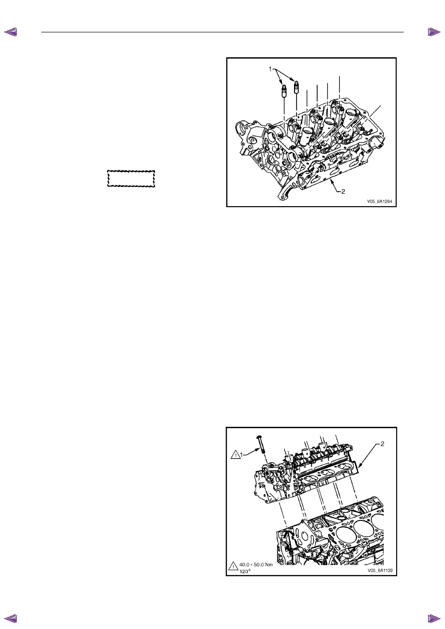
7
Remove the cylinder head attaching bolt (1), eight
places.
8
Remove the cylinder head.
N O T E
There is no bolt fitted to the hole in the rear of
the right-hand-hand cylinder head.
Figure 6A1 – 275
Engine Mechanical – V6
Page 6A1–162
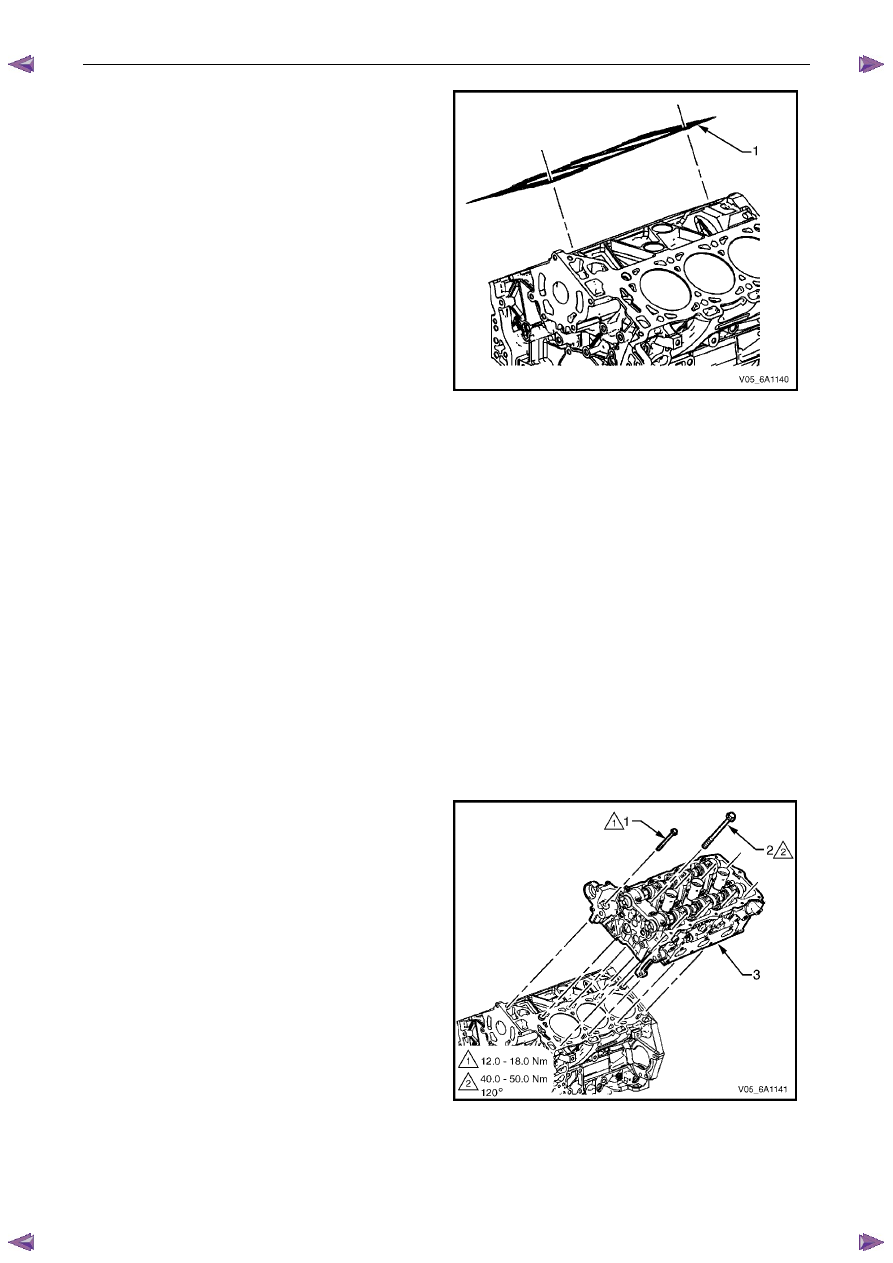
9
Remove and discard the cylinder head gasket (1).
Figure 6A1 – 276
Left-hand Side (Bank 2) Cylinder Head
1
Remove the intake manifold assembly, refer to 3.10
Intake Manifold Assembly – Complete.
2
Remove the exhaust manifold, refer to 3.11
Exhaust Manifold Assembly.
3
Remove the power steering reservoir and pump mounting brackets, refer to 3.8
Power Steering Pump Bracket.
N O T E
Do not disconnect the power steering pipes
and/or hoses.
4
Remove the oil filter adapter upper bolt.
N O T E
Do not remove the oil filter adapter.
5
Remove the engine coolant temperature (ECT) sensor, refer to 6C1-3 Engine Management – V6 – Service
Operations.
6
Remove engine harness ground terminal attaching bolt from cylinder head, refer to 8A Electrical Body & Chassis.
7
Remove the left-hand bank secondary timing chain, refer to 3.16 Timing Chains, Tensioners, Shoes and Guides.
8
Remove the camshaft position actuators, refer to 3.18
Camshaft Sprocket.
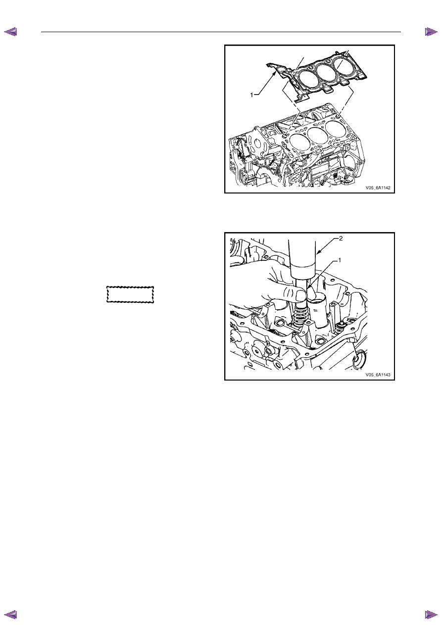
9
Remove the front M8 (1) cylinder head attaching bolt,
two places.
10
Remove the cylinder head attaching bolt (2), eight
places.
11
Remove the cylinder head (3).
Figure 6A1 – 277
Engine Mechanical – V6
Page 6A1–163
12
Remove and discard the cylinder head gasket (1).
Figure 6A1 – 278
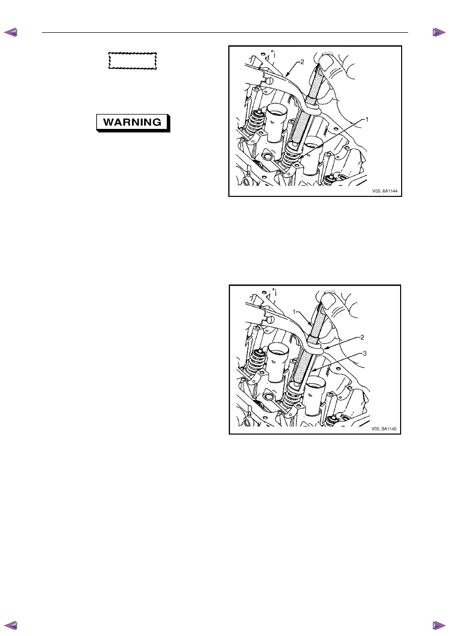
Disassemble
1
Using an appropriately sized deep socket (1) and a
plastic hammer (2), lightly tap on the valve spring
retainer to loosen the valve collets.
CAUTION
Ensure valve heads will not contact anything
during this step in order to avoid bending or
damage.
Figure 6A1 – 279
Engine Mechanical – V6
Page 6A1–164
CAUTION
Do not compress the valve springs less than
24.0 mm. Contact between the valve spring
retainer and the valve stem oil seal can
cause potential valve stem oil seal damage.
Compressed valve springs (1) have high
tension against the valve spring
compressor (2). Valve springs that are not
correctly compressed by, or are released
from the valve spring compressor can be
ejected from the valve spring compressor
with intense force. Use care when
compressing or releasing the valve spring
with the valve spring compressor and when
removing or installing the valve stem keys.
Failing to use care may cause personal
injury.
2
Compress the valve spring (1) using valve spring
compressor Tool No. J-8062 (2) and adaptor Tool No.
EN-46119.
Figure 6A1 – 280
3
Remove the valve collets using Tool EN-46117 (1).
4
Remove the valve spring compressor (2) and the
adapter (3).
Figure 6A1 – 281
Нет комментариевНе стесняйтесь поделиться с нами вашим ценным мнением.
Текст