Isuzu KB P190. Manual — part 318
6E-238 Engine Control System (4JH1)
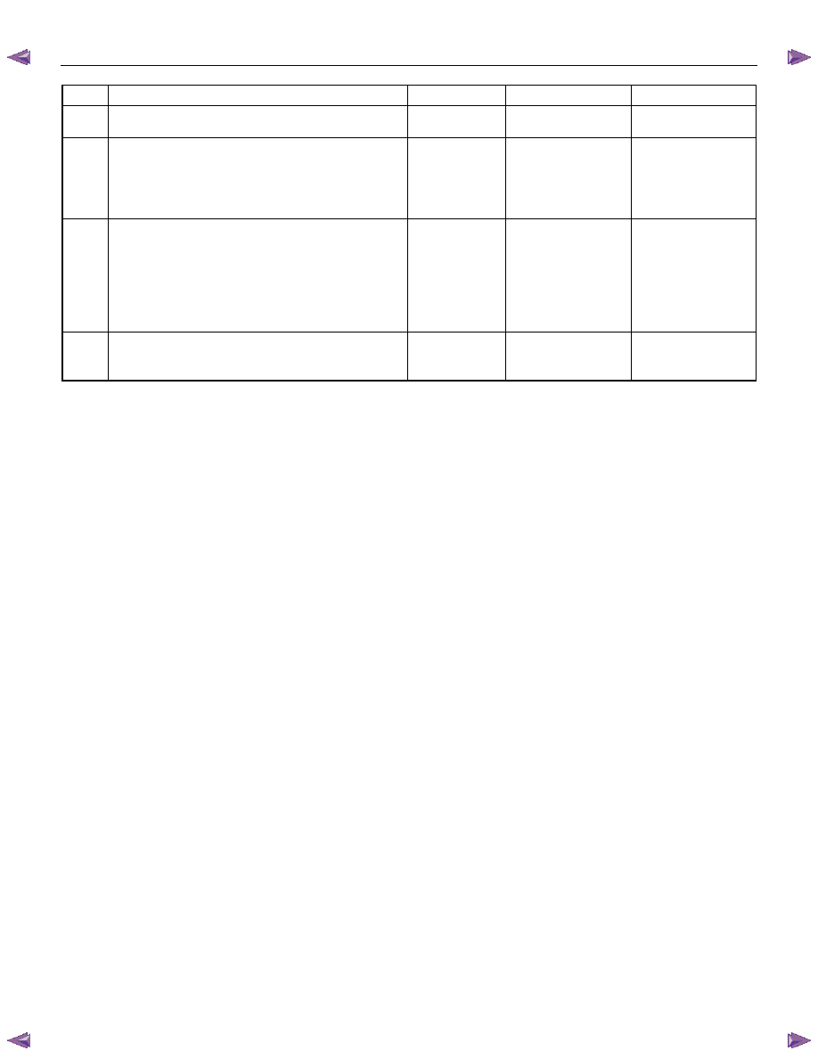
Step Action
Value(s)
Yes
No
5
Repair or replace the IPC (meter assembly).
Did you complete the repair or replacement?
Go to Step 7
6
Important: Replacement ECM must be
programmed.
Replace the ECM. Refer to Engine Control Module
(ECM) Replacement in this section.
Did you complete the replacement?
Go to Step 7
7
1. Reconnect all previously disconnected harness
connector(s).
2. Clear the DTCs with the scan tool.
3. Turn OFF the ignition for 30 seconds.
4. Start the engine.
5. Monitor the DTC Information with the scan tool.
Did the DTC fail this ignition?
Go to Step 2
Go to Step 8
8
Observe the DTC Information with the scan tool.
Are there any DTCs that you have not diagnosed?
Go to Diagnostic
Trouble Code (DTC)
List System
OK

Engine Control System (4JH1) 6E-239
Glow Control System Check
Description
The glow control system consists of the engine control
module (ECM), the glow relay and glow plugs. The glow
control system is operated when the engine coolant
temperature is low, which allows easier engine starting.
The ECM commands the glow relay ON for a certain
length of time at ignition switch is ON with engine OFF.
In after glow phase, the glow plugs remain energized for
a certain period with engine run.
Glow Control Operation
• The pre glow control system operates when the
engine coolant temperature is less than 30
°C
(86
°F).
• The after glow control system operates when the
engine coolant temperature is less than 60
°C
(140
°F).
Glow Control System Check
Schematic Reference: Engine Controls Schematics
Connector End View Reference: Engine Controls
Connector End Views
Step Action
Value(s)
Yes
No
1
Did you perform the Diagnostic System Check-
Engine Controls?
Go to Step 2
Go to Diagnostic
System Check-
Engine Controls
2
1. Install the scan tool.
2. Turn OFF the ignition for 30 seconds.
3. Turn ON the ignition, with the engine OFF.
4. Monitor the Diagnostic Trouble Code (DTC)
Information of the engine control system with the
scan tool and check whether following DTC(s) is
set:
• P0115 (Symptom Code 1 & 2)
• P0380 (Symptom Code 4 & 8)
• P0381 (Symptom Code 4 & 8)
Are any of the above DTC(s) set?
Refer to Applicable
DTC
Go to Step 3
3
1. Turn OFF the ignition.
2. Make sure the metal bus bar that connects
switched battery voltage supply terminal (E-49)
and all glow plugs is secured tightly.
3. Turn ON the ignition, with the engine OFF
4. Connect a test lamp between the metal bus bar
(glow plug power supply E-49 terminal) and a
known good ground.
5. Perform the Glow Relay test with the scan tool.
6. Command the Glow Relay ON with the scan tool
while observing the test lamp.
Does the test lamp turn ON only when commanded
ON with the scan tool?
Go to Step 4
Go to Step 5
4
1. Turn OFF the ignition.
2. Remove the metal bus bar from the glow plugs.
3. Measure resistance of each glow plug between
the glow plug terminals and a known good
ground. Make sure to record all measurements
and take them quickly as to not allow engine
temperature changes between measurements.
Are the resistances within the specified value each
other?
1Ω
System OK
Go to Step 15

6E-240 Engine Control System (4JH1)
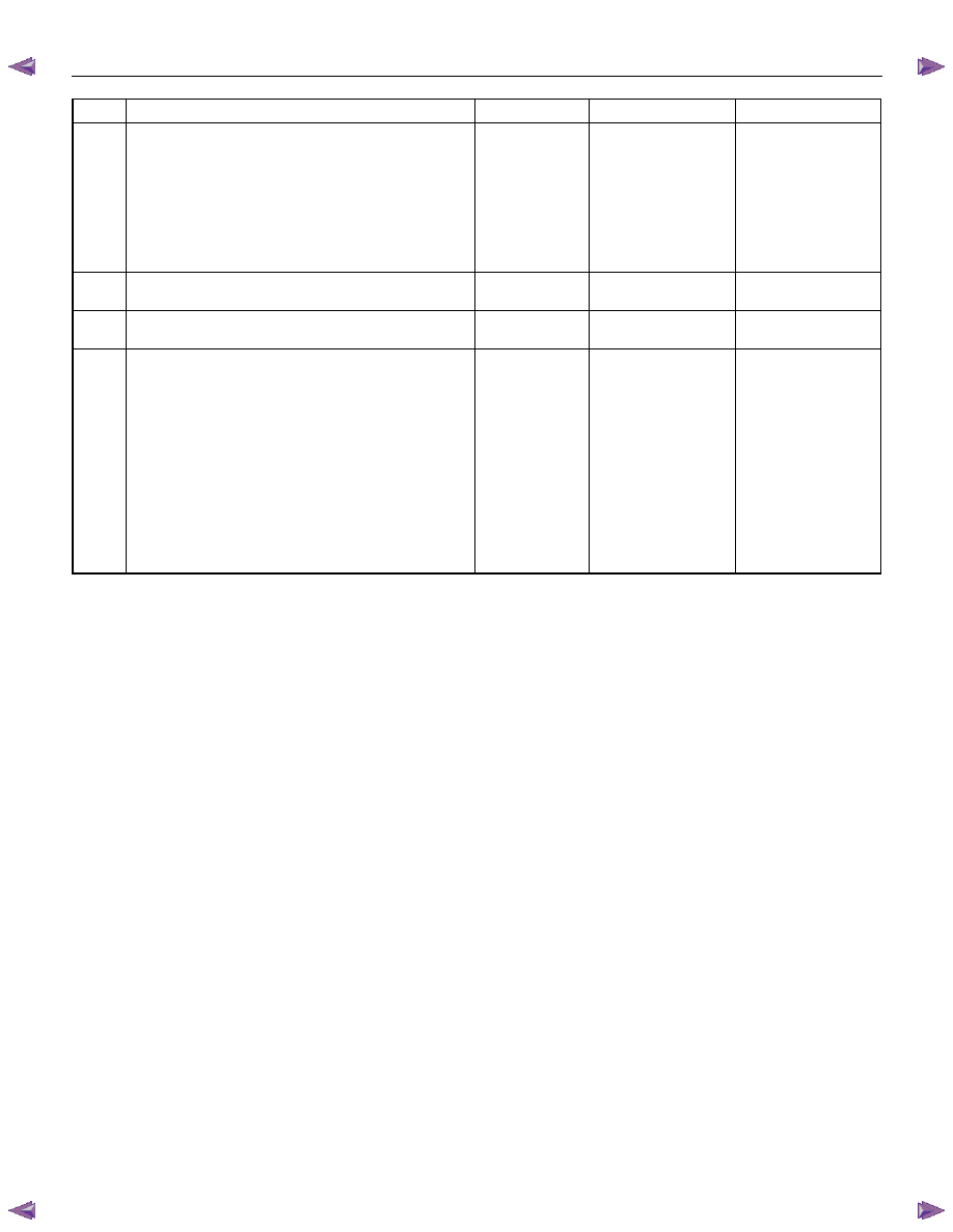
Step Action
Value(s)
Yes
No
5
1. Turn OFF the ignition.
2. Replace the glow relay with the starter relay or
replace with a known good relay.
3. Turn ON the ignition, with the engine OFF.
4. Connect a test lamp between the metal bus bar
(glow plug power supply E-49 connector) and a
known good ground.
5. Perform the Glow Relay test with the scan tool.
6. Command the Glow Relay ON with the scan tool
while observing the test lamp.
Does the test lamp turn ON only when commanded
ON with the scan tool?
Go to Step 9
Go to Step 6
6
Inspect the Glow (60A) slow blow fuse (SBF-8) in the
engine room fuse block.
Is the Glow (60A) slow blow fuse (SBF-8) open?
Go to Step 10
Go to Step 7
7
1. Turn OFF the ignition.
2. Remove the glow relay in the engine room relay
block.
3. Connect a test lamp between the voltage feed
circuit of the glow relay terminal (pin 4 of X-5
connector) and a known good ground.
4. Turn ON the ignition, with the engine OFF.
Does the test lamp illuminate?
Go to Step 8
Go to Step 11
8
1. Turn ON the ignition, with the engine OFF.
2. Connect a test lamp between the power supply
circuit of glow plugs (pin 1 of X-5 connector) and
a known good ground.
Does the test lamp illuminate?
Go to Step 13
Go to Step 12
9
1. Turn OFF the ignition.
2. Inspect for an intermittent and for poor
connections at the glow relay terminals (pins 1
and 4 of X-5 connector).
3. Repair the connection(s) as necessary.
Did you find and correct the condition?
Go to Step 16
Go to Step 14
10
1. Replace the Glow (60A) slow blow fuse (SBF-8).
If the slow blow fuse continues to open, repair
the short to ground on a circuit fed by the slow
blow fuse or check for a shorted attached
component.
2. Repair the short to ground or replace the
component as necessary.
Did you complete the repair?
Go to Step 16
11
Repair the open circuit in the battery voltage supply
circuit between the Glow (60A) slow blow fuse (SBF-
8) and the glow relay (pin 1 of X-5 connector).
Did you complete the repair?
Go to Step 16
12 Repair the open circuit in the switched battery
voltage supply circuit between the glow relay (pin 1
of X-5 connector) and the glow plugs (E-49
terminal).
Did you complete the repair?
Go to Step 16
Engine Control System (4JH1) 6E-241
Step Action
Value(s)
Yes
No
13
Important: The glow plugs may be burnt out if the
battery voltage supply circuit is shorted to a voltage
source.
Repair the short to battery or ignition voltage on the
switched battery voltage supply circuit between the
glow relay (pin 1 of X-5 connector) and the glow
plugs (E-49 terminal).
Did you complete the repair?
Go to Step 16
14
Replace the glow relay.
Did you complete the replacement?
Go to Step 16
15
Replace the appropriate glow plug.
Did you complete the replacement?
Go to Step 16
16 1.
Reconnect all previously disconnected
components, relay, fuse or harness connector(s).
2. Turn OFF the ignition for 30 seconds.
3. Turn ON the ignition, with the engine OFF.
4. Connect a test lamp between the metal bus bar
(glow plug power supply E-49 connector) and a
known good ground.
5. Perform the Glow Relay test with the scan tool.
6. Command the Glow Relay ON with the scan tool
while observing the test lamp.
Does the test lamp turn ON only when commanded
ON with the scan tool?
Go to Step 4
Go to Step 2
Нет комментариевНе стесняйтесь поделиться с нами вашим ценным мнением.
Текст