Isuzu KB P190. Manual — part 319

6E-242 Engine Control System (4JH1)
DTC A/C Compressor System Check
Description
When air conditioning (A/C) and blower fan are
selected, and if the system has a sufficient refrigerant
charge. A 12-volt signal is supplied to the A/C request
input of the Engine Control Module (ECM). The A/C
request signal may be temporarily canceled during
system operation by the electronic thermostat in the
evaporator to prevent the evaporator icing. Also, it is
cancelled when the pressure switch detected abnormal
pressure in the line. When the A/C request signal is
received by the ECM, the ECM supplies a ground from
the A/C compressor relay if the engine operating
conditions are within acceptable ranges. With the A/C
compressor relay energized, voltage is supplied to the
compressor clutch coil. The ECM will enable the
compressor clutch to engage whenever A/C has been
selected with the engine running and enable conditions
are met.
Condition for Running the A/C Compressor:
• The engine is running.
• The A/C switch is ON.
• The engine coolant temperature (ECT) is less than
105
°C(221°F).
A/C Compressor System Check
Schematic Reference: Engine Controls Schematics
Connector End View Reference: Engine Controls
Connector End Views or Engine Control Module (ECM)
Connector End Views
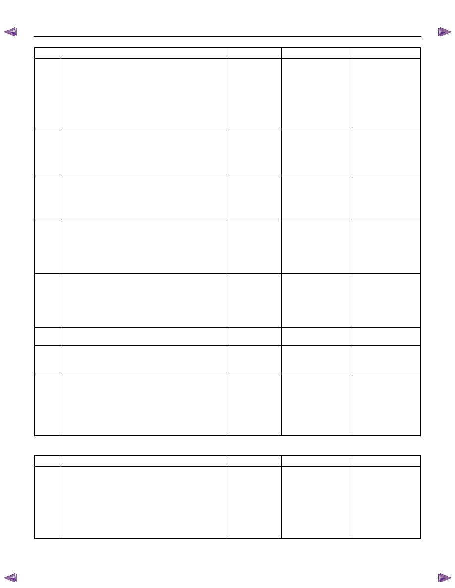
Chart 1 of 2
Step Action
Value(s)
Yes
No
1
Did you perform the Diagnostic System Check-
Engine Controls?
Go to Step 2
Go to Diagnostic
System Check –
Engine Controls
2
1. Install the scan tool.
2. Turn OFF the ignition for 30 seconds.
3. Turn ON the ignition, with the engine OFF.
4. Monitor the Diagnostic Trouble Code (DTC)
Information of the engine control system with the
scan tool and check whether following DTC(s) is
set:
• P0115 (Symptom Code 1 & 2)
• P0645 (Symptom Code 4 & 8)
Are any of the above DTC(s) set?
Refer to Applicable
DTC
Go to Step 3
3
1. Turn ON the ignition, with the engine OFF.
2. Turn ON the blower motor switch.
Does the blower motor turn ON and operate
correctly?
Go to Step 4
Refer to Applicable
Diagnostic Chart in
Heating & Air
Conditioning
Section
4
1. Turn OFF the blower motor switch.
2. Keep the A/C switch OFF.
Does the A/C Request Signal parameter indicate
OFF?
Go to Step 5
Go to Chart 2 of 2
with heater Step 1
OR
Go to Chart 2 of 2
without heater Step
1
5
1. Start the engine and let the engine idle.
2. Keep the blower motor switch OFF.
3. Keep the A/C switch OFF.
Does the A/C compressor clutch keep OFF
(disengage)?
Go to Step 6
Go to Step 11
6
1. Turn ON the blower motor switch.
2. Keep the A/C switch OFF.
Does the A/C compressor clutch keep OFF
(disengage)?
Go to Step 7
Go to Chart 2 of 2
with heater Step 7
OR
Go to Chart 2 of 2
without heater Step
4

Engine Control System (4JH1) 6E-243
Step Action
Value(s)
Yes
No
7
1. Turn OFF the blower motor switch.
2. Turn ON the A/C switch.
Does the A/C compressor clutch keep OFF
(disengage)?
Go to Step 8
Go to Chart 2 of 2
with heater Step 8
OR
Go to Chart 2 of 2
without heater Step
10
8
1. Turn ON the blower motor switch.
2. Keep the A/C switch ON.
Does the A/C compressor clutch ON and OFF
(engage and disengage) periodically within the
Condition for Running the A/C Compressor?
Go to Step 9
Go to Step 10
9
Does the air flow cool enough.
System OK
Refer to Applicable
Diagnostic Chart in
Heating & Air
Conditioning
Section
10
Does the A/C Relay Command parameter indicate
ON at previous step?
Go to Step 14
Go to Chart 2 of 2
with heater Step 9
OR
Go to Chart 2 of 2
without heater Step
11
11
1. Turn OFF the ignition.
2. Disconnect the A/C compressor clutch harness
connector (E-3).
3. Start the engine.
Does the A/C compressor clutch ON (engage)?
Go to Step 22
Go to Step 12
12
1. Turn OFF the ignition.
2. Remove the A/C compressor relay from the
engine room relay block.
3. Connect a test lamp between the A/C
compressor clutch voltage supply circuit (pin 2 of
X-14 connector) and a known good ground.
4. Turn ON the ignition, with the engine OFF.
Does the test lamp illuminate?
Go to Step 13
Go to Step 21
13
Repair the short to battery or ignition voltage on the
A/C compressor voltage feed circuit between the
A/C compressor relay (pin 2 of X-14 connector) and
the A/C compressor (E-3).
Did you complete the repair?
Go to Step 23
14
1. Turn OFF the ignition.
2. Remove the A/C compressor relay from the
engine room fuel block.
3. Connect a test lamp between the voltage feed
circuit of the relay switch side terminal (pin 1 of
X-14 connector) and known good ground.
4. Turn ON the ignition, with the engine OFF.
Does the test lamp illuminate?
Go to Step 15
Go to Step 17
15
1. Keep the ignition ON, with the engine OFF.
2. Disconnect the test lamp.
3. Connect a 3-amp fused jumper wire between
both switch side terminals of the A/C compressor
relay (pins 1 and 2 of X-14 connector).
Does the A/C compressor clutch click (engage)?
Go to Step 19
Go to Step 16
6E-244 Engine Control System (4JH1)
Step Action
Value(s)
Yes
No
16
1. Keep the ignition ON, with the engine OFF.
2. Keep 3-amp fused jumper wire with connected.
3. Disconnect A/C compressor clutch harness
connector.
4. Connect a test lamp between A/C compressor
voltage feed circuit (E-3) and a known good
ground.
Does the test lamp illuminate?
Go to Step 20
Go to Step 18
17
Repair the open circuit or high resistance on the
relay switch side voltage feed circuit between the
A/C compressor relay (pin 1 of X-14 connector) and
the A/C (10A) fuse (EB-13).
Did you complete the repair?
Go to Step 23
18
Repair the open circuit or high resistance on the
relay switched voltage supply circuit between the
A/C compressor relay (pin 2 of X-14 connector) and
the A/C compressor clutch (pin 1 of E-3 connector).
Did you complete the repair?
Go to Step 23
19
1. Turn OFF the ignition.
2. Inspect for an intermittent and for poor
connections at the A/C compressor relay
terminals (pins 3 and 5 of X-14 connector).
3. Repair the connection(s) as necessary.
Did you find and correct the condition?
Go to Step 23
Go to Step 21
20
1. Turn OFF the ignition.
2. Inspect for an intermittent and for a poor
connection at the harness connector of the A/C
compressor clutch (E-3).
3. Repair the connection(s) as necessary.
Did you find and correct the condition?
Go to Step 23
Go to Step 22
21
Replace the A/C compressor relay.
Did you complete the replacement?
Go to Step 23
22
Replace the A/C compressor. Refer to Heating and
Air Conditioning section.
Did you complete the replacement?
Go to Step 23
23 1. Reconnect all previously disconnected fuse,
relay or harness connector(s).
2. Turn OFF the ignition for 30 seconds.
3. Turn ON the ignition, with the engine OFF.
4. Turn ON the blower motor switch.
Does the blower motor turn ON and operate
correctly?
Go to Step 4
Refer to Applicable
Diagnostic Chart in
Heating & Air
Conditioning
Section
Chart 2 of 2 with heater
Step Action
Value(s)
Yes
No
1
1. Turn OFF the ignition.
2. Replace the thermo relay with the horn relay or
replace with a known good relay.
3. Turn OFF the blower motor switch.
4. Turn OFF the A/C switch.
5. Turn ON the ignition, with the engine OFF.
Does the A/C Request Signal parameter indicate
OFF?
Go to Step 33
Go to Step 2

Engine Control System (4JH1) 6E-245
Step Action
Value(s)
Yes
No
2
1. Turn OFF the ignition.
2. Remove the thermo relay from the engine room
relay block.
3. Turn ON the ignition, with the engine OFF.
Does the A/C Request Signal parameter indicate
OFF?
Go to Step 3
Go to Step 4
3
1. Turn OFF the ignition.
2. Reinstall the thermo relay.
3. Remove the radiator grille in order to access the
pressure switch.
4.
Disconnect the pressure switch harness
connector (C-24).
5. Turn OFF the blower motor switch.
6. Turn OFF the A/C switch.
7. Turn ON the ignition, with the engine OFF.
Does the A/C Request Signal parameter indicate
OFF?
Go to Step 6
Go to Step 5
4
Repair the short to battery or ignition voltage on the
thermo relay signal input circuit between the thermo
relay (pin 1 of X-15 connector) and the engine
control module (ECM) (pin 33 of C-56 connector).
Did you complete the repair?
Go to Step 39
5
Repair the short to ground between the thermo relay
(pin 5 of X-15 connector) and pressure switch (pin 1
of C-24 connector).
Did you complete the repair?
Go to Step 39
6
Repair the short to ground between the pressure
switch (pin 2 of C-24 connector) and the electronic
thermostat (pin 2 of C-55 connector), then electronic
thermostat (pin 1 of C-56 connector) and the A/C
switch (pin 5 of B-57 connector).
Did you complete the repair?
Go to Step 39
7
1. Test the A/C switch circuits shorted each other.
(pins 1 and 5 of B-57 connector).
2. Repair the circuits as necessary.
Did you find and correct the condition?
Go to Step 39
Go to Step 36
8
1. Test the circuit between the blower motor switch
(pin 1 of B-13 connector) and the A/C switch (pin
1 of B-57 connector) for a short to ground.
2. Repair the circuits as necessary.
Did you find and correct the condition?
Go to Step 39
Go to Step 37
9
Inspect the A/C (10A) fuse (EB-13) in the engine
room fuse block.
Is the A/C (10A) fuse (EB-13) open?
Go to Step 10
Go to Step 11
10
1. Replace the A/C (10A) fuse (EB-13). If the fuse
continues to open, repair the short to ground on
a circuit fed by the fuse or check for a shorted
attached component.
2. Repair the short to ground or replace the
component as necessary.
Did you complete the repair?
Go to Step 39
Нет комментариевНе стесняйтесь поделиться с нами вашим ценным мнением.
Текст