Isuzu KB P190. Manual — part 884
Engine Management – V6 – Service Operations
Page 6C1-3–12
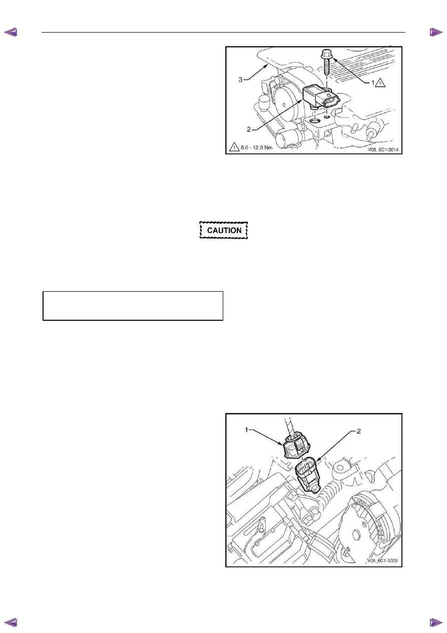
3
Remove the bolt (1) attaching the BARO sensor (2) to
the upper intake manifold (3).
4
Remove the BARO sensor from the manifold by first,
twisting the sensor to release it, and then pulling it
upwards to remove it.
Figure 6C1-3 – 6
Reinstall
Reinstallation of the barometric pressure (BARO) sensor is the reverse of the removal procedure, noting the following:
Ensure the BARO sensor is fully seated
before tightening the attaching bolt to the
specified torque.
1
Reinstall the BARO sensor bolt and tighten to the correct torque specification.
Barometric pressure sensor
attaching bolt
torque specification . . . . . . . . ...8.0 – 12.0 Nm
2
Road test the vehicle and check for correct operation.
2.4
Camshaft Position Sensor
Remove
1
Turn the ignition switch off.
2
Disconnect the wiring harness connector (1) from the
CMP sensor (2).
Figure 6C1-3 – 7
Engine Management – V6 – Service Operations
Page 6C1-3–13
Clean the area around the CMP sensor before
removal to avoid debris from entering the
engine.
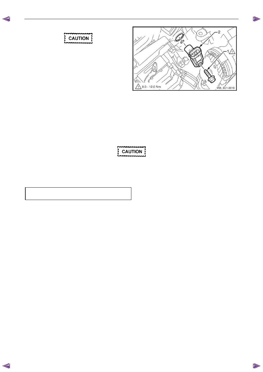
3
Remove the CMP sensor attaching bolt (1).
4
Remove the CMP sensor (2) by first twisting the
sensor to release it, and then pulling it away from the
front engine cover to remove it.
Figure 6C1-3 – 8
Reinstall
Reinstallation of the camshaft position (CMP) sensor is the reverse of the removal procedure, noting the following:
1
Lubricate the CMP sensor O-ring with clean engine oil.
2
Reinstall the CMP sensor by pushing in on the sensor to engage the sensor O-ring in the front engine cover.
Ensure the CMP sensor is fully seated before
tightening the attaching bolt to the specified
torque.
3
Reinstall the CMP sensor bolt and tighten to the correct torque specification.
Camshaft position sensor attaching bolt
torque specification . . . . . . . . ...8.0 – 12.0 Nm
4
Road test the vehicle and check for correct operation, taking particular note there is no engine oil leak from the
CMP sensor.
2.5
Crankshaft Position Sensor
Remove
1
Turn the ignition switch off.
2
Raise the front of the vehicle and support on safety stands, refer to 0A General Information for location of the
jacking points.

Engine Management – V6 – Service Operations
Page 6C1-3–14
3
Disconnect the wiring harness connector (1) from the
crankshaft position (CKP) sensor (2).
Figure 6C1-3 – 9
Clean the area around the CKP sensor before
removal to avoid debris from entering the
engine.
4
Remove the CKP sensor attaching bolt (1).
5
Remove the CKP sensor (2), by first twisting the
sensor to release it, and then pulling it away from the
engine block to remove it.
6
If required, test the CKP sensor, refer to the Test in
this Section.
Figure 6C1-3 – 10
Engine Management – V6 – Service Operations
Page 6C1-3–15
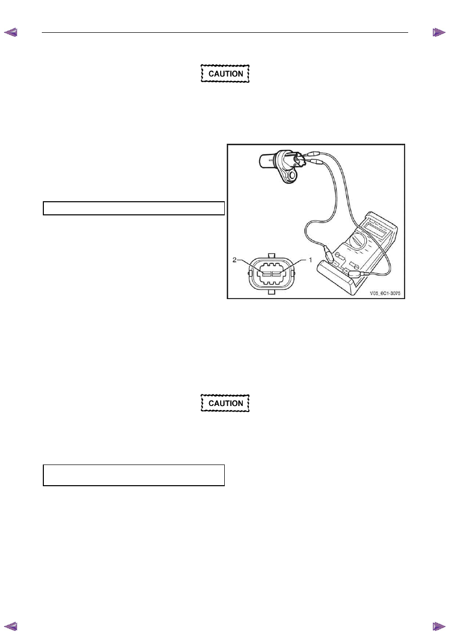
Test
To prevent component and damage use
connector test adaptor kit J 35616-A.
Resistance Check
1
Connect a digital ohmmeter using connector test
adaptor kit J 35616-A to the crankshaft position (CKP)
sensor.
2
Measure the resistance across terminals 1 and 2.
3
Compare the reading against the specification.
CKP sensor resistance @ 20°C . . . . 850 – 1040
Ω
4
If the resistance is not within specification, replace the
CKP sensor.
Figure 6C1-3 – 11
Reinstall
Reinstallation of the crankshaft position (CKP) sensor is the reverse of the removal procedure, noting the following:
1
Lubricate the CKP sensor O-ring with clean engine oil.
2
Reinstall the CKP sensor by pushing down on the sensor to engage the sensor O-ring in the engine block.
Ensure the CKP sensor is fully seated before
tightening the attaching bolt to the specified
torque.
3
Reinstall the CKP sensor bolt and tighten to the correct torque specification.
Crankshaft position sensor attaching bolt
torque specification . . . . . . . . ...8.0 – 12.0 Nm
4
Road test the vehicle and check for correct operation, taking particular note there is no engine oil leak from the
CKP sensor.
Нет комментариевНе стесняйтесь поделиться с нами вашим ценным мнением.
Текст