Isuzu KB P190. Manual — part 680
Engine Mechanical – V6
Page 6A1–241
2
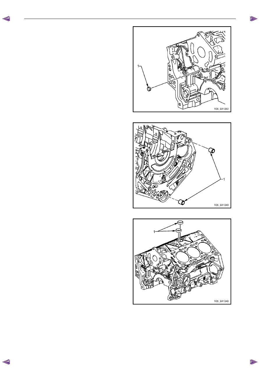
Install a new front oil gallery expansion plug (1).
Figure 6A1 – 451
3
Install the cylinder block-to-transmission alignment
dowels (1).
Figure 6A1 – 452
4
Place RTV sealant on new coolant expansion plugs
(1) and install the new coolant expansion plugs.
Figure 6A1 – 453
Engine Mechanical – V6
Page 6A1–242
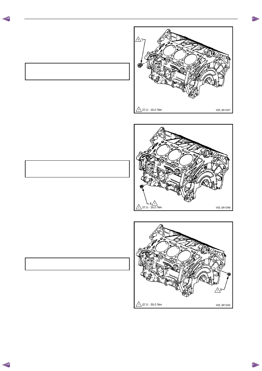
5
Install the left-hand side M20 oil gallery threaded plug
(1) and tighten to the correct torque specification.
Left-hand side M20 cylinder block
oil gallery threaded plug
torque specification . . . . . . . . .27.0 – 35.0 Nm
Figure 6A1 – 454
6
Install the left-hand side M14 coolant drain threaded
plug (1) and tighten to the correct torque specification.
Left-hand side M14 cylinder block
coolant drain threaded plug
torque specification . . . . . . . . .27.0 – 35.0 Nm
Figure 6A1 – 455
7
Install the M14 rear oil gallery threaded plug (1) and
tighten to the correct torque specification.
M14 cylinder block rear oil gallery
threaded plug torque specification . . ..27.0 – 35.0 Nm
Figure 6A1 – 456
Engine Mechanical – V6
Page 6A1–243
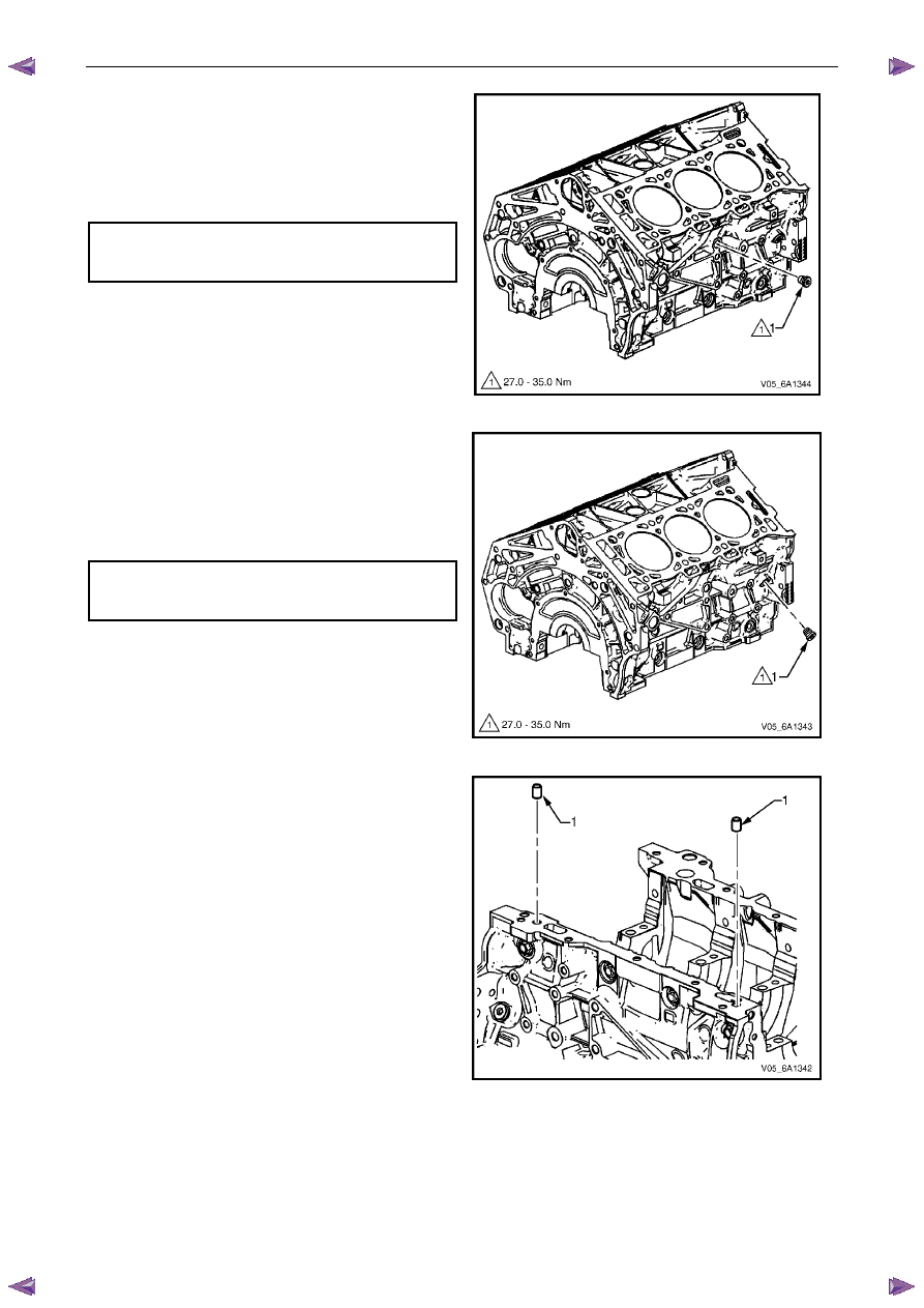
8
Install the right-hand side M14 coolant drain threaded
plug (1) and tighten to the correct torque specification.
Right-hand side M14 cylinder block
coolant drain threaded plug
torque specification . . . . . . . . .27.0 – 35.0 Nm
Figure 6A1 – 457
9
Install the right-hand side M14 oil gallery threaded
plug (1) and tighten to the correct torque specification.
Right-hand side M14 cylinder block
oil gallery threaded plug
torque specification . . . . . . . . .27.0 – 35.0 Nm
Figure 6A1 – 458
10
Install the cylinder block-to-oil pan alignment
dowels (1).
Figure 6A1 – 459
Engine Mechanical – V6
Page 6A1–244
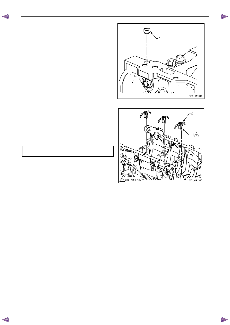
11
Install the new right-hand front oil pan rail oil gallery
expansion plug (1).
Figure 6A1 – 460
12
Install the oil jet (2), three places.
13
Install the oil jet attaching bolt (1), three places and
tighten to the correct torque specification.
Oil jet attaching bolt
torque specification . . . . . . . . ...8.0 – 12.0 Nm
Figure 6A1 – 461
4.8 Thread
Repairs
General Information
The thread repair process involves a solid, thin walled, self-locking, carbon steel, bushing type insert. During the insert
installation process, the installation driver tool cold-rolls the bottom internal threads and expands the bottom external
threads of the insert into the base material. This action mechanically locks the insert into place.
This Section describes the recommended method of repairing threads in three specific areas of the engine.
•
general thread repair,
•
cylinder block main bearing cap bolt hole thread repair, and
•
cylinder head bolt hole thread repair.
For detailed descriptions of all thread specifications used refer to 4.9
Thread Repair Specifications.
The drill-bit and counter-bore tool from the thread repair kit, Tool No. J-42385-700 and J-42385-2000 are designed for
use with either a suitable tap wrench or drill motor. Limited access and larger hole repair may process better using a tap
wrench. An extension from Tool J 43965 may also be required to drive the thread repair tooling dependent on access to
the hole being repaired. Use only a tap wrench when tapping the hole and during installation of the insert.
Нет комментариевНе стесняйтесь поделиться с нами вашим ценным мнением.
Текст