Isuzu KB P190. Manual — part 937
Powertrain Interface Module – V6
Page 6E1–87
16 Special
Tools
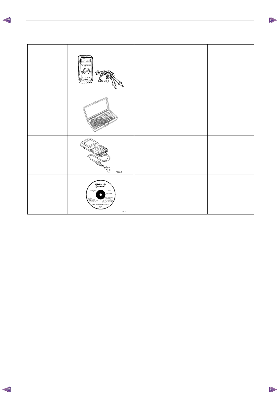
Tool
Number Illustration
Description Tool
Classification
3588
Digital Multimeter
Previously released as J39200 or
equivalent.
NOTE: The instrument must have 10
mega ohms impedance and be
capable of reading frequencies.
Mandatory
J35616
Connector Test Adaptor Kit
Used when carrying out electrical
diagnostic circuit checks.
Desirable
70000861
Tech 2 Diagnostic Scan Tool
Previously released.
Mandatory
N/A
Technical Information System (TIS)
CD ROM
Available to Authorised Dealers.
Mandatory

Exhaust System – V6
Page 6F – 1
6F
Exhaust System – V6
A T T E N T I O N
Before performing any service operations or other procedure described in this Section, refer to
1.3
WARNING, CAUTION and NOTES for correct workshop practices with regard to safety and / or
property damage.
1
General Information . . . . . . . . . . . . . . . . . . . . . . . . . . . . . . . ...2
1.1
Emission Reductions . . . . . . . . . . . . . . . . . . . . . . . . . . . . . . . . . . . 2
Euro 3 Emissions Standards . . . . . . . . . . . . . . . . . . . . . . . . . . . . . . . . 3
1.2
General Description. . . . . . . . . . . . . . . . . . . . . . . . . . . . . . . . . . . ... 4
Service Notes . . . . . . . . . . . . . . . . . . . . . . . . . . . . . . . . . . . . . . . 5
1.3
WARNING, CAUTION and NOTES. . . . . . . . . . . . . . . . . . . . . . . . . . . . . . . 5
1.1 Definition of WARNING, CAUTION and NOTE Statements. . . . . . . . . . . . . . . . . . ... 5
WARNING defined . . . . . . . . . . . . . . . . . . . . . . . . . . . . . . . . . . . . 5
CAUTION defined . . . . . . . . . . . . . . . . . . . . . . . . . . . . . . . . . . . .. 5
NOTE defined . . . . . . . . . . . . . . . . . . . . . . . . . . . . . . . . . . . . . 6
2
Front and Centre Exhaust Pipe . . . . . . . . . . . . . . . . . . . . . . . . . . . .7
Removal . . . . . . . . . . . . . . . . . . . . . . . . . . . . . . . . . . . . . . . . .. 7
Reinstallation . . . . . . . . . . . . . . . . . . . . . . . . . . . . . . . . . . . . . . . 8
3
Silencer and Rear Exhaust Pipe. . . . . . . . . . . . . . . . . . . . . . . . . . . 9
Removal . . . . . . . . . . . . . . . . . . . . . . . . . . . . . . . . . . . . . . . . .. 9
Reinstallation . . . . . . . . . . . . . . . . . . . . . . . . . . . . . . . . . . . . . . . 9
4
Torque Wrench Specifications. . . . . . . . . . . . . . . . . . . . . . . . . . . 10
Exhaust System – V6
Page 6F – 2
1 General
Information
Information contained within this section describes the general exhaust system.
1.1 Emission
Reductions
Through developments in various vehicle emissions reduction systems, significant reductions in emissions have been
achieved. The developments have been primarily concerned with refinements in engine calibration and the optimisation
of exhaust system catalytic converter configurations.
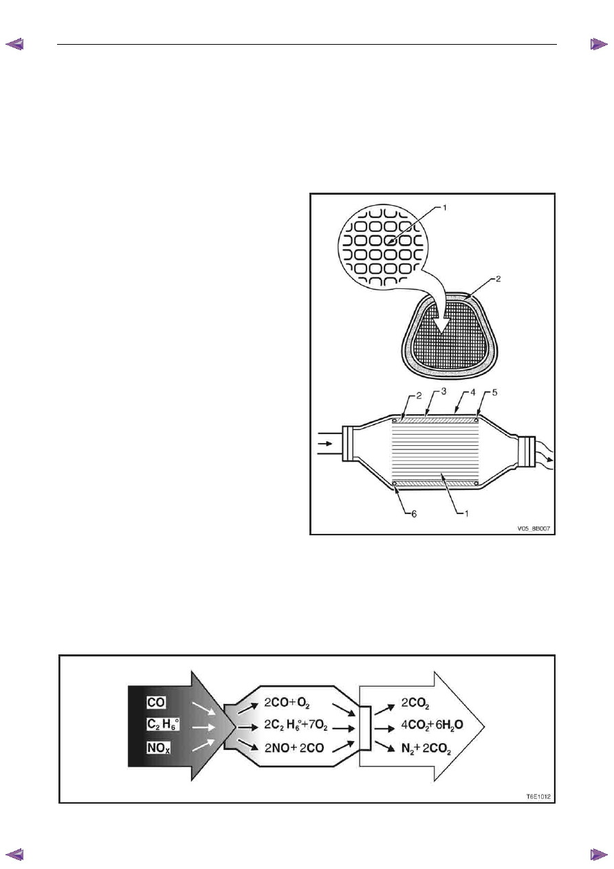
The catalytic converter is similar to a muffler in appearance
however, within the outer stainless steel shell (4), there is a
ceramic monolith (1) which is honeycombed in the direction
of exhaust flow, as shown. The ceramic monolith is
surrounded by a mat (2), which has the primary function of
holding the monolith firmly in place to prevent any contact
with the inner shell (3). A mesh seal (5 and 6) at each end
of the converter prevents exhaust gases from fouling and
eroding the mat.
Surfaces of the ceramic monolith that are exposed to
exhaust gases are coated with a catalytic material. This
material contains rhodium and platinum, which act to
facilitate the chemical reactions necessary to oxidise carbon
monoxide and hydrocarbons into harmless carbon dioxide.
Figure 6F– 1
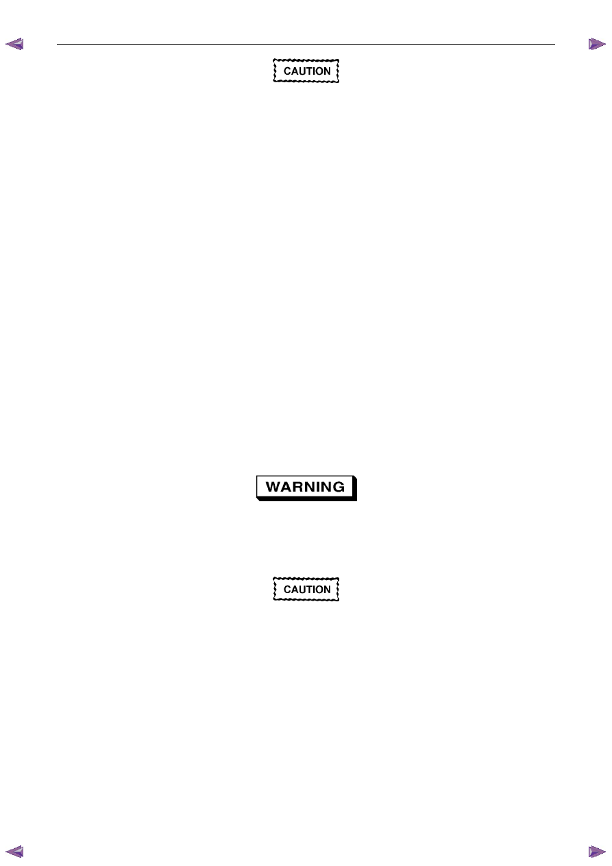
The catalytic converter is a substance that accelerates a chemical reaction without itself being changed. Engine exhaust
gases contain carbon monoxide (CO), hydrocarbons (HC) and oxides of nitrogen (NO
x
). When the exhaust gases flow
through the monolith, reactions with the catalytic converter occur. CO and HC are converted by oxidation with oxygen
(O
2
) in the exhaust gases to produce carbon dioxide (CO
2
) and water vapour (H
2
O). NO
x
is converted by reduction with
CO to produce nitrogen (N
2
) and CO
2
. The converter is called a three-way type because it simultaneously converts three
components of exhaust gas (CO, HC and NO
x
) to harmless natural gases, refer to Figure 6F– 2
Figure 6F– 2
Exhaust System – V6
Page 6F – 3
The Catalytic converter can be damaged or
rendered ineffective, if:
• operated outside the limits of the closed
loop mixture control system
• the engine burns excessive amount of oil
• the exhaust temperature at the converter
is too high (exceeds 840°C).
The catalytic material is very sensitive to the effects of a rich or lean fuel mixture, which may cause the temperature of
the converter to rise rapidly. The catalytic converter normally operates at approximately 600
°C.
The catalytic converter is also sensitive to the use of leaded petrol. Using leaded fuel can cause deposits to form in the
converter, which restrict exhaust flow and prevent the catalyst from working. This will result in an increase in exhaust
backpressure and converter temperature.
N O T E
The use of unleaded petrol results in black
tailpipe deposits rather than the grey colour that
some people may normally associate with an
acceptable combustion condition. This black
colour resulting from the use of unleaded fuel
does not necessarily indicate a state of poor
engine tune. For V6 engines, Refer to: 6C1 – 1
Engine Management General Information.
Euro 3 Emissions Standards
The Euro 3 emissions standard is a European standard which aims at setting vehicle emissions targets to encourage
vehicle manufacturers to reduce harmful vehicle emissions such as Carbon Monoxide (CO), Hydrocarbons (HC) and the
various oxides of Nitrogen (NOx).
This vehicle is fitted with a supplemental
restraint system (SRS). Refer to section 9A
Restraints, in order to determine whether you
are performing service on or near the SRS
components or the SRS wiring.
Always use the correct fastener in the proper
location. When you replace a fastener, use
ONLY the exact part number for that
application. Isuzu will identify those fasteners
that require a replacement after removal and
fasteners that require thread lockers or thread
sealant. Unless otherwise specified, do not
use supplemental coatings (Paints, greases
or corrosion inhibitors) on thread fasteners or
fastener joints. Generally such coatings
adversely effect the fastener torque and the
joint clamping force, and may damage the
fastener. When you install fasteners, use the
correct tightening sequence and torque
specifications.
Нет комментариевНе стесняйтесь поделиться с нами вашим ценным мнением.
Текст