Isuzu KB P190. Manual — part 190
BRAKES 5C-61
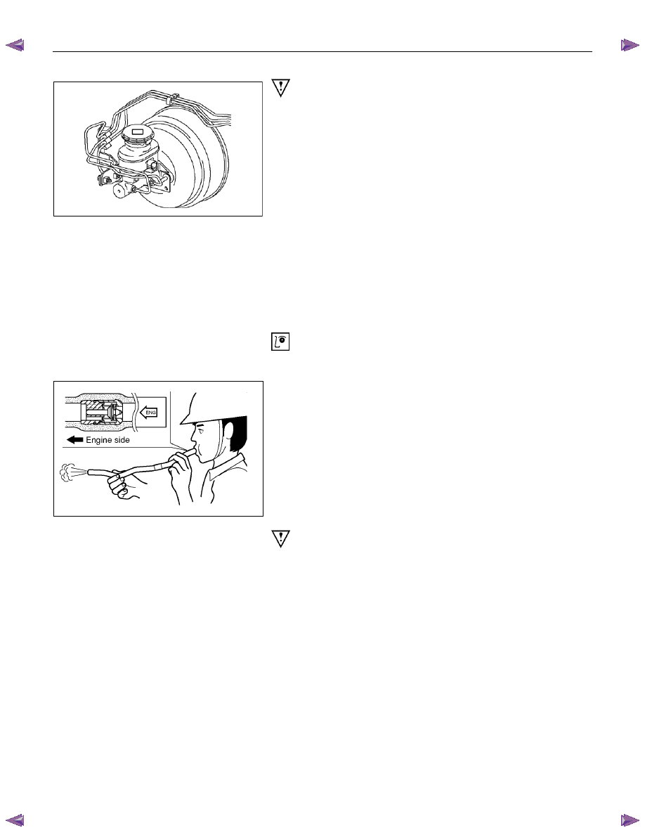
RTW75CSH002701
Important Operation-Removal
1. Brake pipe
When hurdling, be careful not to spill brake fluid over the
painted surfaces, as damage to the paint finish will result.
2. Master Cylinder Fixing Nut
3. Bracket
4. Master Cylinder Assembly
NOTE:
When removing the master cylinder from the vacuum booster,
be sure to get rid of the internal negative pressure of the
vacuum booster (by, for instance, disconnecting the vacuum
hose) in advance.
If any negative pressure remains in the vacuum booster, the
piston may possibly come out when the master cylinder is
being removed, letting the brake fluid run out.
While removing the master cylinder, do not hold the piston as it
can be easily pulled out.
Inspection and Repair
Vacuum Hose (The built in check valve)
360R300002
1) Inspect the check valve, which is installed inside the
vacuum hose.
2) Blow air into the hose from the booster side as shown in
the illustration. The air should pass freely through the
hose.
3) Blow air into the hose from the engine side. The check
valve should close to block the passage of air.
The vacuum hose and built-in check valve must be
replaced as a set if either is found to be defective.
Important Operation-Installation
10. Vacuum Booster Assembly
Note:
• Adjustment of push rod of vacuum booster is not carried
out. When vacuum booster is damaged it exchanges for a
new article. (Push rod is adjusted)
• Measurement of primary piston position by the side of
master cylinder is unnecessary.
9. Spacer
8. Gasket
7. Vacuum Booster Fixing Nut
6. Snap Pin
Install the vacuum booster assembly to the dash panel and
pedal mounting bracket.
5C-62 BRAKES
360r300003
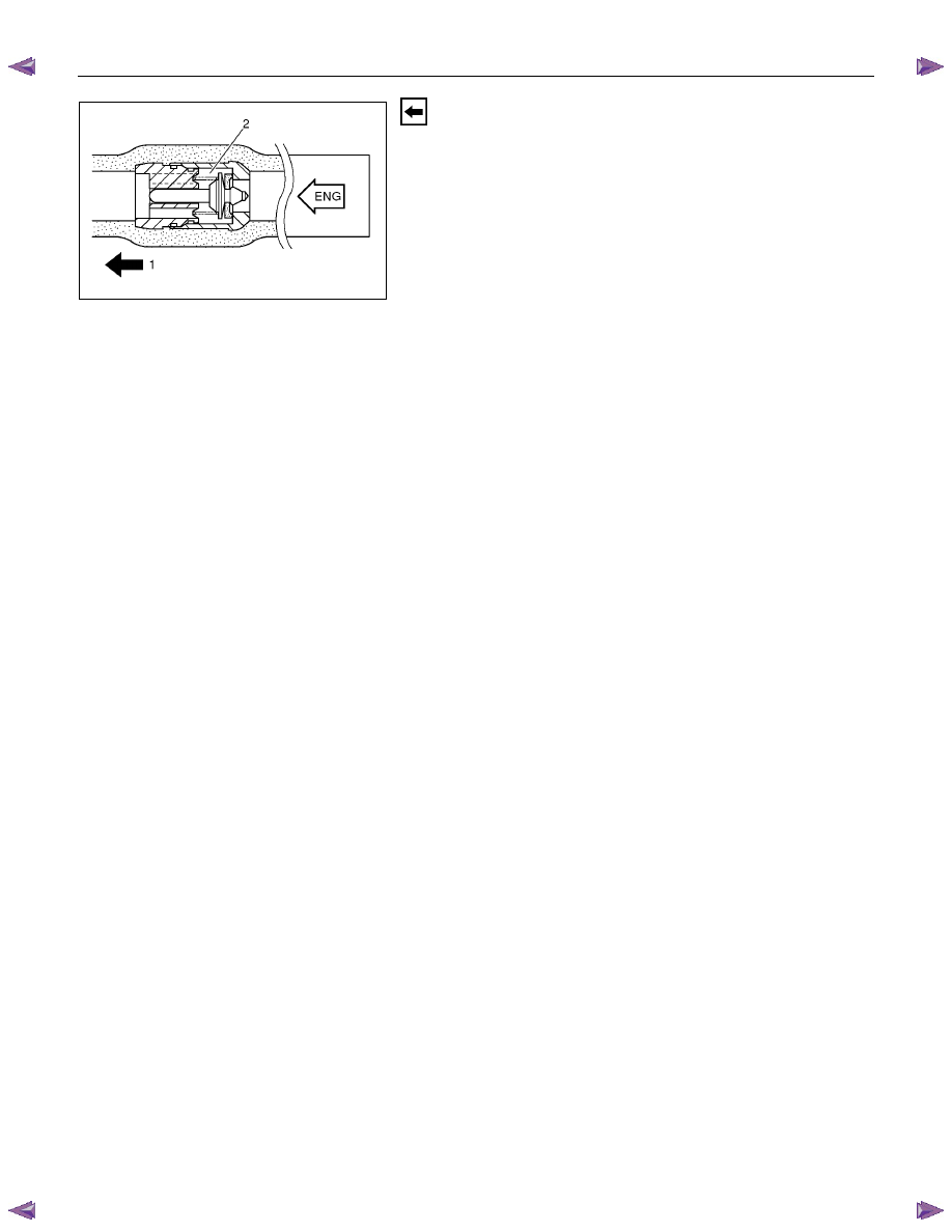
5. Vacuum Hose
The check valve (2) is built-in to the vacuum hose.
When installing the vacuum hose make sure that the arrow on
the hose is facing the engine (1).
Note:
• Do not apply oil to the vacuum hose.
• Installation direction is very important. The booster will not
operate if the vacuum hose is installed in the wrong
direction.
BRAKES 5C-63
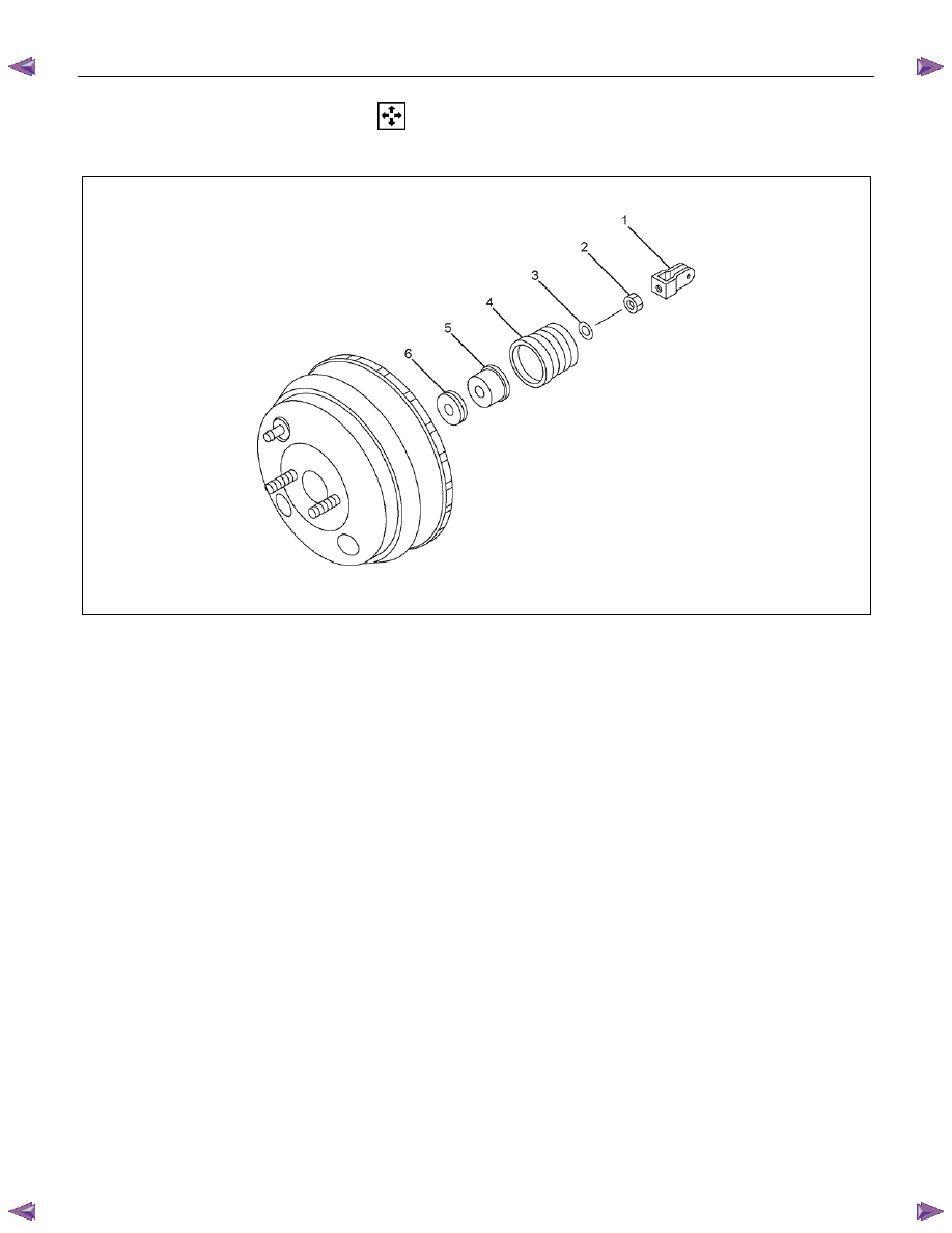
DISASSEMBLY
VACUUM BOOSTER ASSEMBLY
Disassembly Steps
1. Clevis; Yoke
2. Nut; VLV rod
3. Retainer; Guard
4. Guard; VLV body
5.
Silencer
6.
Filter
5C-64 BRAKES
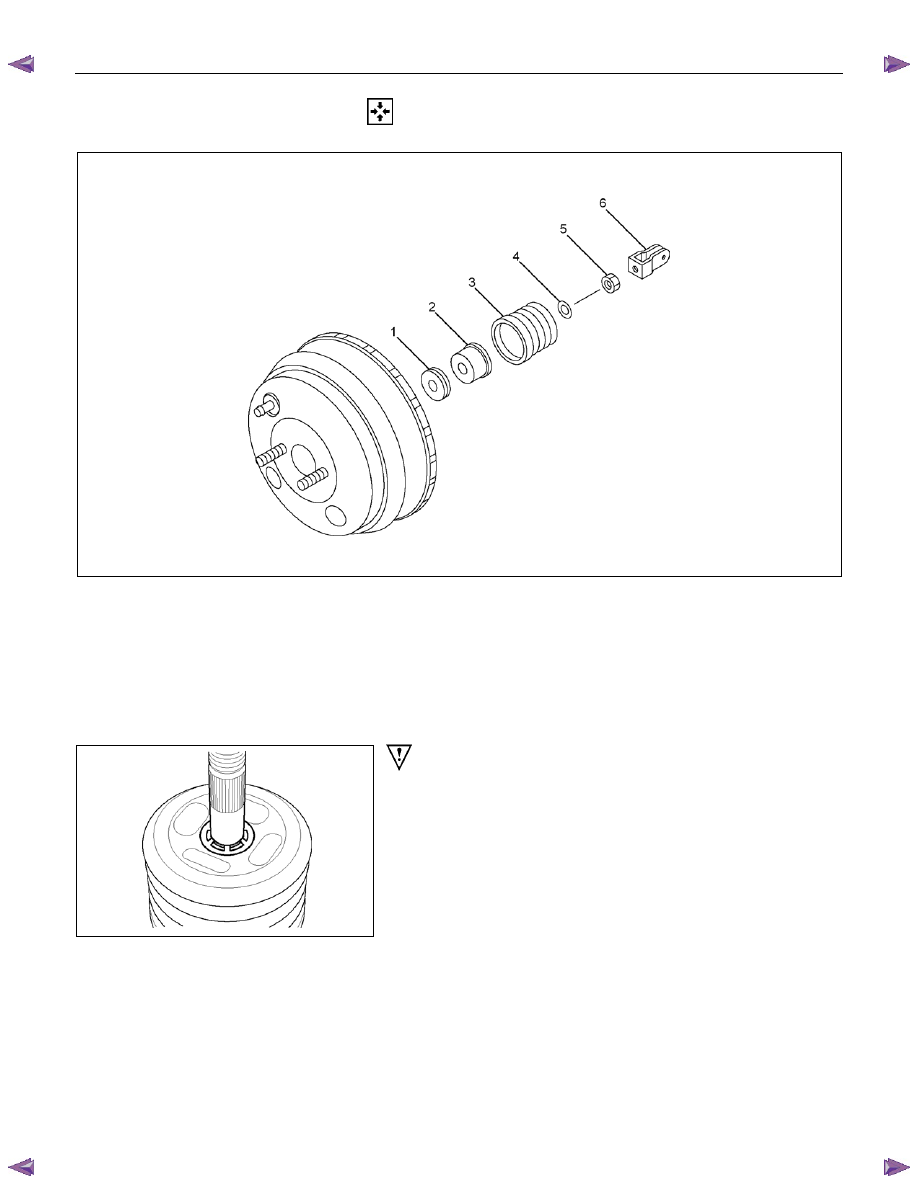
REASSEMBLY
VACUUM BOOSTER ASSEMBLY
Reassembly Steps
1.
Filter
2.
Silencer
3. Guard; VLV body
▲ 4. Retainer; Guard
▲ 5. Nut; VLV rod
▲ 6. Clevis; Yoke
RTW75CSH002901
Important Operations
4. Retainer; Guard
Ensure that the lug of the inner surface is fitted into the groove
of the ROD.
5. Nut; VLV Rod
Install the nut.
Нет комментариевНе стесняйтесь поделиться с нами вашим ценным мнением.
Текст