Isuzu KB P190. Manual — part 79

POWER-ASSISTED STEERING SYSTEM 3B-55
Check clearance between capsule and bracket. It must
be less than 1 mm (0.039 in).
431RW031
Column Universal Joint (between the
power steering unit and the steering shaft)
If resistance is felt when checked by rotating the joint,
replace the lower second steering shaft.
Shaft Universal Joint (between the lower
second steering shaft and the second
steering shaft)
If resistance is felt when checked by rotating the joint,
replace the second steering shaft assembly.
Tilt Mechanism
The tilt mechanism should move smoothly.
While locking the tilt mechanism, be sure the steering
column is latched securely by pushing the steering
wheel upward and downward.
Installation
1. Align the setting mark (1) on the second steering
shaft and the steering column assembly (applied at
disassembly).
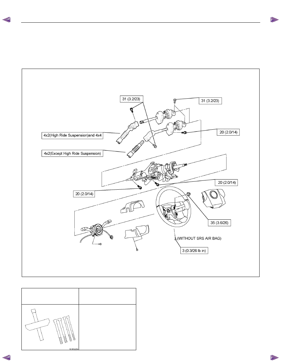
2. Connect the steering column assembly to the second
steering shaft. Tighten the bolts to the specified
torque.
Torque: 31 N
⋅⋅⋅⋅m (3.2 kgf⋅⋅⋅⋅m/23 lb⋅⋅⋅⋅ft)
RTW53BSH00301
3. Thread the steering column assembly through the
hole in the dashpanel. Temporarily tighten the
steering column and the second steering shaft fixing
bolts.
4. Align the setting marks (applied at disassembly) and
connect the lower second steering shaft and the
second steering shaft. Tighten the universal joint
bolts to the specified torque.
Torque: 31 N
⋅⋅⋅⋅m (3.2 kgf⋅⋅⋅⋅m/23 lb⋅⋅⋅⋅ft)
5. Tighten the steering column fixing bolt (pedal bracket
side) to the specified torque (This bolt was
temporarily tightened in Step 3).
Torque: 20 N
⋅⋅⋅⋅m (2.0 kgf⋅⋅⋅⋅m/14 lb⋅⋅⋅⋅ft)
6. Tighten the second steering shaft fixing bolt to the
specified torque (This bolt was temporarily tightened
in Step 3)
Torque: 20 N
⋅⋅⋅⋅m (2.0 kgf⋅⋅⋅⋅m/14 lb⋅⋅⋅⋅ft)
7. Tighten the steering column fixing bolt (dashpanel
side) to the specified torque (This bolt was
temporarily tightened in Step 3).
Torque: 20 N
⋅⋅⋅⋅m (2.0 kgf⋅⋅⋅⋅m/14 lb⋅⋅⋅⋅ft)
8. Install combination switch and SRS coil assembly.
After installation of combination switch assembly,
connect the combination switch wiring harness
connector and the SRS 2-way connector located
under the steering column.
3B-56 POWER-ASSISTED STEERING SYSTEM
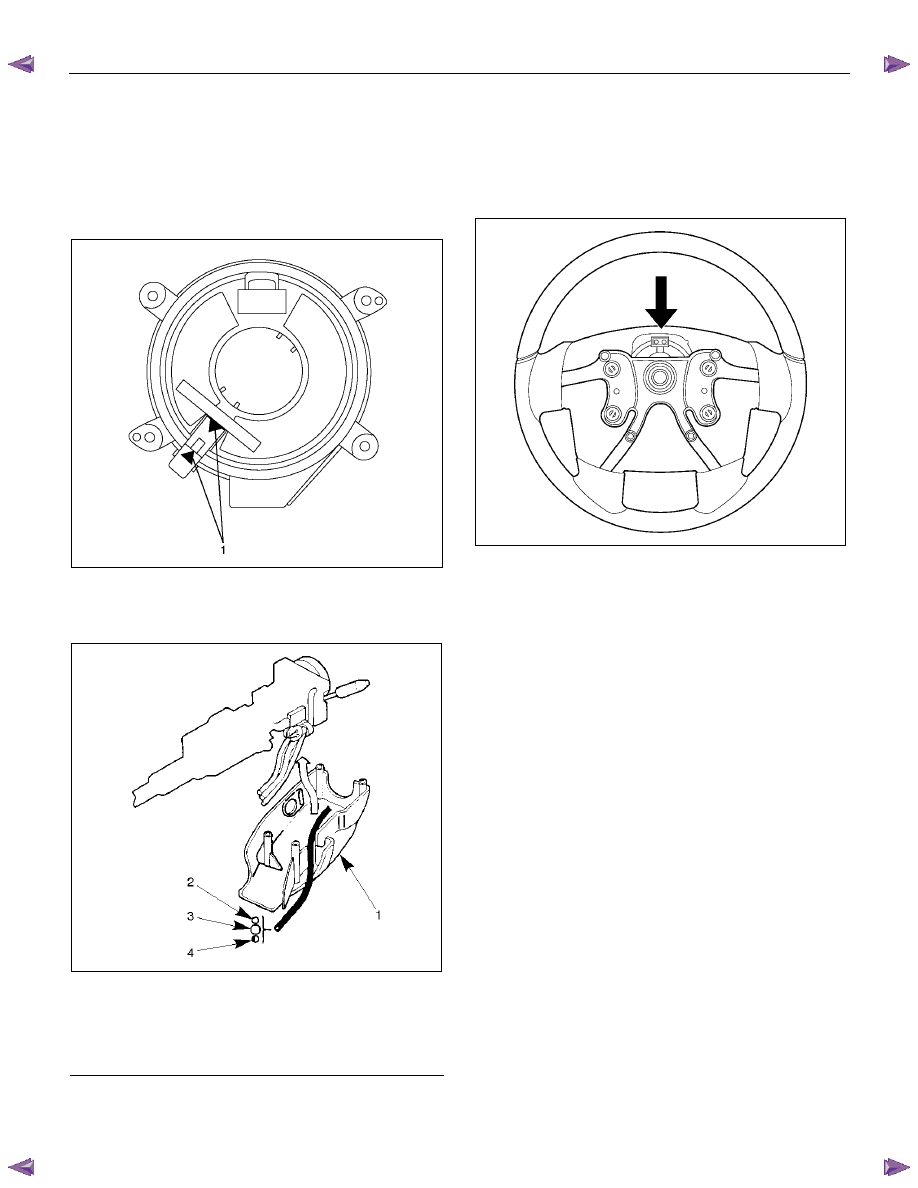
9. Turn the SRS coil fully counterclockwise, return
about 3 turns and align the neutral mark (1). (with
SRS air bag)
CAUTION: When turning the SRS coil fully
counterclockwise, stop turning if resistance is felt.
Further forced turning may damage to the cable in
the SRS coil.
826RW014
10. When installing the steering column cover, be sure to
route each wiring harness as illustrated so that the
harnesses do not catch any moving parts.
825RW017
Legend
(1) Steering Column Cover
(2) Starter Switch Harness
(3) Combination Switch Harness
(4) Inflator Module Harness
11.
Install steering wheel and align the setting marks
made when removing.
Refer to the adjustment method in case a mark has
not been applied in this section.
NOTE: Confirm SRS and horn harness connector is
fixed by the steering wheel.
RTW73BSH000701
CAUTION: Never apply force to the steering wheel in
the direction of the shaft by using a hammer or
other impact tools in an attempt to remove the
steering wheel. The steering shaft is designed as an
energy absorbing unit.
12. Tighten the steering wheel fixing nut to the specified
torque.
Torque: 35 N
⋅⋅⋅⋅m (3.6 kgf⋅⋅⋅⋅m/26 lb⋅⋅⋅⋅ft)
13.
Support the module and carefully connect the
module connector and horn lead, then install inflator
module.
NOTE: Pass the lead wire through the tabs on the
plastic cover (wire protector) of inflator to prevent lead
wire from being pinched.
14. Tighten bolts to specified torque.
Torque: 3 N
⋅⋅⋅⋅m (0.3 kgf⋅⋅⋅⋅m/26 lb⋅⋅⋅⋅in)
15. Install driver knee bolster (reinforcement).
16. Install instrument panel lower cover.
17. Install the engine hood opening lever.
18. Connect the yellow 2-way SRS connector and horn
lead located under the steering column.
19. Connect the battery "-" terminal cable (with SRS air
bag).
POWER-ASSISTED STEERING SYSTEM 3B-57
System Inspection (with SRS air bag)
Turn the ignition switch to "ON" while watching warning
light.
The light should flash 7 times and then go off. If lamp
does not operate correctly, refer to Restraints section.
3B-58 POWER-ASSISTED STEERING SYSTEM
Supplemental Restraint System Steering Wheel & Column and
Associated Parts
Main Data and Specifications
Torque Specifications
N
⋅m (kgf⋅m/lb⋅ft)
RTW73BLF000501
Special Tools
ILLUSTRATION
TOOL NO.
TOOL NAME
5-8521-0016-0
(J-29752)
Steering wheel remover
Нет комментариевНе стесняйтесь поделиться с нами вашим ценным мнением.
Текст