Isuzu KB P190. Manual — part 78
POWER-ASSISTED STEERING SYSTEM 3B-51
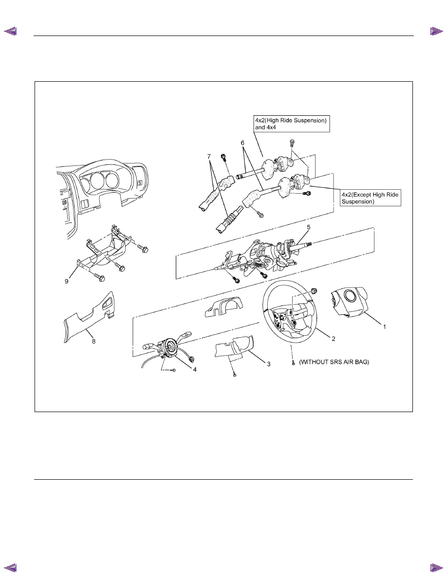
Steering Column
Steering Column and Associated Parts
RTW73BLF000301
Legend
(1) Inflator Module or Horn Pad
(2) Steering Wheel
(3) Steering Column Cover
(4) Combination Switch and SRS Coil Assembly
(5) Steering Column Assembly
(6) Second Steering Shaft
(7) Lower Second Steering Shaft
(8) Instrument Panel Lower Cover
(9) Driver Knee Bolster (reinforcement)
Removal
1. Turn the steering wheel so that the vehicle's wheels
are pointing straight ahead.
2. Turn the ignition switch to "LOCK".
3. Disconnect the battery "-" terminal cable, and wait at
least 5 minutes. (with SRS air bag)
4. Disconnect the yellow 2-way SRS connector located
under the steering column. (with SRS air bag)
3B-52 POWER-ASSISTED STEERING SYSTEM
CAUTION: The wheel of the vehicle must be straight
ahead and the steering column in the "LOCK"
position before disconnecting the steering column
from the steering gear. Failure to do so will cause
the SRS coil assembly to lose its centering which
will cause damage to the SRS coil assembly (with
SRS air bag).
5. Remove the engine hood opening lever and
steering lower cover.
6. Remove the driver knee bolster (reinforcement).
7. Disable the SRS (Refer to "Disabling the SRS" in
this section) (with SRS air bag).
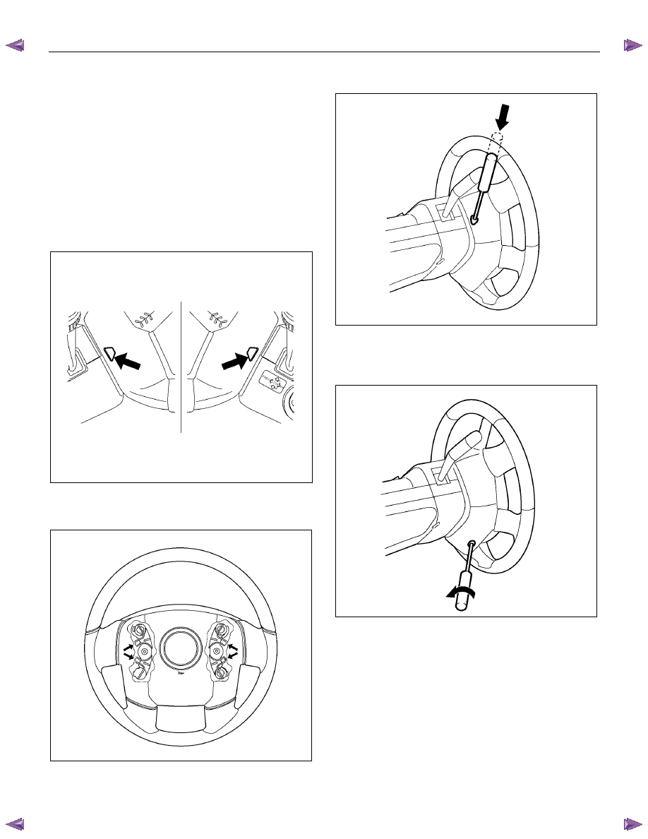
8. Check the holes on both sides of the steering cover
(with SRS air bag).
060R300025
9. Check the position of the pins in thier holes. Push
the pin in the direction of the arrow (with SRS air
bag).
RTW73BSH000101
10. Push the four pins with a φ 5~6 mm (0.20~0.24 in)
bar (with SRS air bag).
060R300031
11. Cancel the lock to release the four pins (with SRS
air bag).
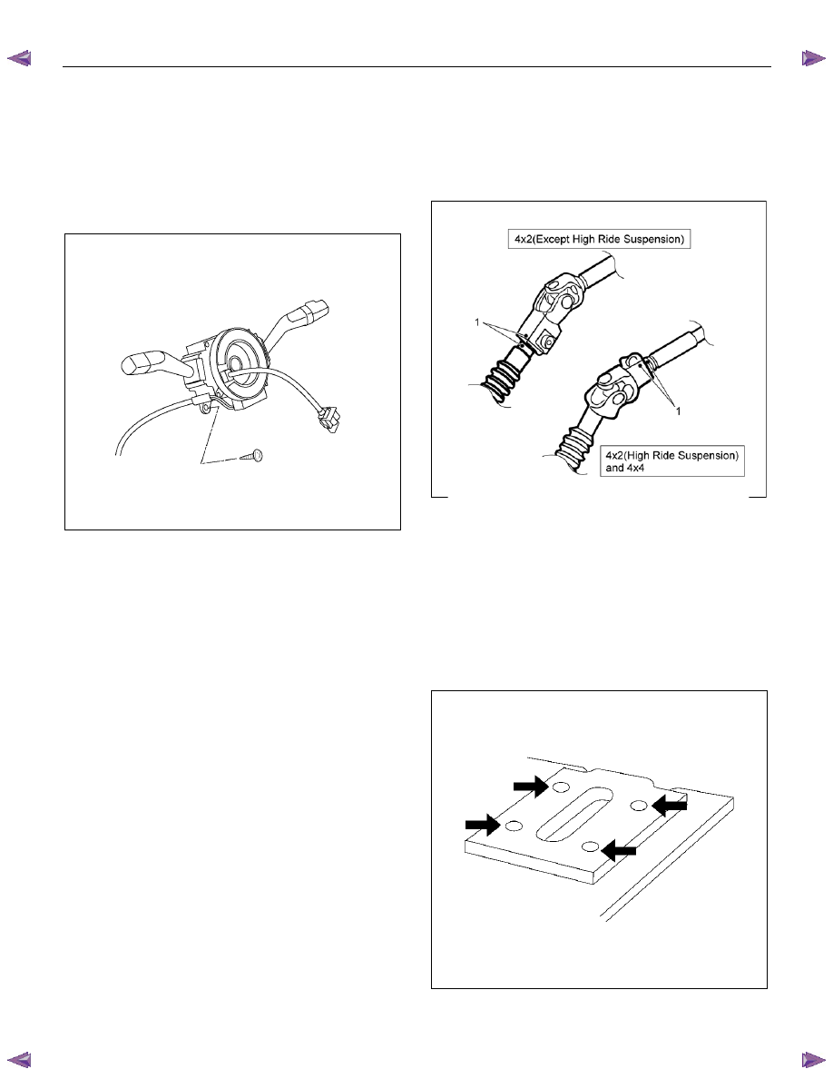
12. Loosen the horn pad fixing screw at the rear of the
steering wheel (without SRS air bag).
430R300009
POWER-ASSISTED STEERING SYSTEM 3B-53
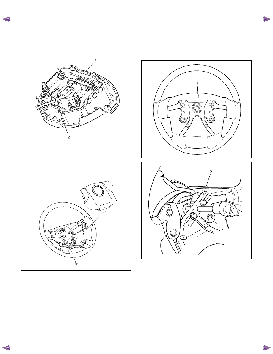
13. Disconnect the SRS air bag connector (1) and horn
lead connector (2) located behind the air bag
assembly and remove the air bag assembly (with
SRS air bag).
RTW73BSH001101
14. Remove the horn pad and the horn leads at the
center of the wheel (without SRS air bag).
NOTE: It should be removed first from the bottom
spokes.
RTW73BSH000601
15. Apply a setting mark (1) across the steering wheel
and shaft so parts can be reassembled in their
original position. Move the front wheels to the
straight ahead position, then use steering wheel
remover 5-8521-0016-0 (2) to remove the steering
wheel.
RTW73BSH000501
RTW73BSH001301
3B-54 POWER-ASSISTED STEERING SYSTEM
16. Remove steering column cover.
17. Disconnect the wiring harness connectors located
under the steering column.
18. Remove the combination switch assembly with SRS
coil.
NOTE: The SRS coil is a part of the combination switch
assembly, which cannot be replaced separately.
Therefore, be sure not to remove the SRS coil from the
combination switch assembly.
RTW73BSH001001
19. Disconnect the starter switch harness connector
located under the steering column, then remove
lock cylinder assembly.
20. Apply a setting mark (1) across the universal joint
and steering shaft to reassemble the parts in their
original position, then remove steering column
assembly and second shaft.
NOTE: A setting mark can be easily made if the shaft is
withdrawn a little by loosening the steering shaft
universal joint.
RTW53BSH000301
Inspection
If abnormal conditions are found during inspection,
replace the steering column assembly.
Column Capsules
Check capsules on steering column bracket assembly;
all must be securely seated in bracket slots and
checked for any loose condition when pushed or pulled
by hand.
431RW030
Нет комментариевНе стесняйтесь поделиться с нами вашим ценным мнением.
Текст