Isuzu KB P190. Manual — part 77

POWER-ASSISTED STEERING SYSTEM 3B-47
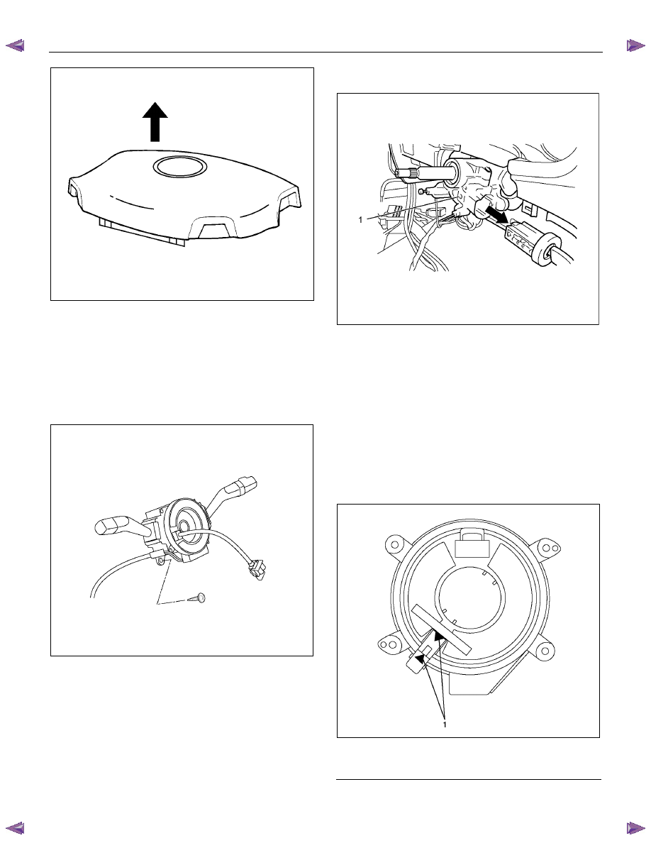
13. Disconnect the SRS air bag connector (1) and horn
lead connector (2) located behind the air bag
assembly and remove the air bag assembly (with
SRS air bag).
RTW73BSH001101
14. Remove the horn pad and the horn leads at the
center of the wheel (without SRS air bag).
NOTE: It should be removed first from the bottom
spokes.
RTW73BSH000601
15. Apply a setting mark (1) across the steering wheel
and shaft so parts can be reassembled in their
original position.
RTW73BSH000501
16. Move the front wheels to the straight ahead position,
then use steering wheel remover 5-8521-0016-0 (2)
to remove the steering wheel.
CAUTION: Never apply force to the steering wheel in
the direction of the shaft by using a hammer or
other impact tools in an attempt to remove the
steering wheel. The steering shaft is designed as an
energy absorbing unit.
RTW73BSH001301
WARNING: THE INFLATOR MODULE SHOULD
ALWAYS BE CARRIED WITH THE COVER AWAY
FROM YOUR BODY AND SHOULD ALWAYS BE
LAID ON A FLAT SURFACE WITH THE COVER SIDE
UP. THIS IS NECESSARY BECAUSE A FREE SPACE
IS PROVIDED TO ALLOW THE AIR CUSHION TO
EXPAND IN THE UNLIKELY EVENT OF
ACCIDENTAL DEPLOYMENT. OTHERWISE,
PERSONAL INJURY MAY RESULT (with SRS air
bag).
3B-48 POWER-ASSISTED STEERING SYSTEM
430R300007
17. Remove steering column cover.
18. Disconnect the wiring harness connectors located
under the steering column.
19. Remove the combination switch assembly with SRS
coil.
NOTE: The SRS coil is a part of the combination switch
assembly, which cannot be replaced separately.
Therefore, be sure not to remove the SRS coil from the
combination switch assembly (with SRS air bag).
RTW73BSH001001
20. Turn the ignition switch to the ACC position.
21. Insert a pin (1) into the hole and push on it. Pull the
key cylinder free.
RUW53BSH000101
Installation
1. Install lock cylinder assembly.
2. Install the combination switch assembly with SRS
coil (with SRS air bag).
3. Turn the SRS coil fully counterclockwise, return
about 3 turns and align the neutral mark (with SRS
air bag).
CAUTION: When turning the SRS coil fully
counterclockwise, stop turning if resistance is felt.
Further forced turning may damage the cable in the
SRS coil (with SRS air bag).
826RW014
Legend
(1) Neutral mark

POWER-ASSISTED STEERING SYSTEM 3B-49
825RS048
4. Install the driver knee bolster assembly.
5. Install the steering lower cover and engine hood
opening lever.
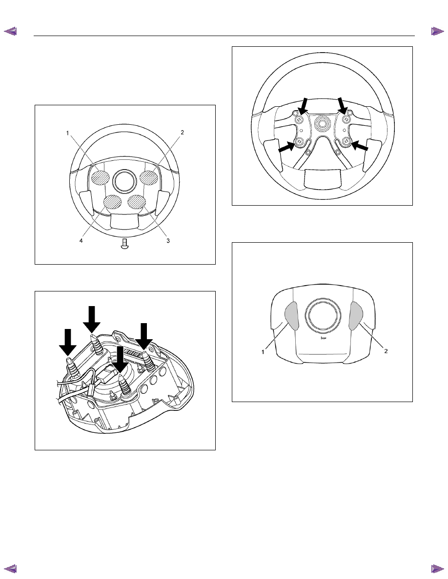
6. Install the steering wheel and align the setting marks.
Refer to the adjustment method in case a mark has
not been applied in this section.
NOTE: Confirm SRS and horn harness connector is
fixed by the steering wheel.
RTW73BSH000701
CAUTION: Never apply force to the steering wheel in
the direction of the shaft by using a hammer or
other impact tools in an attempt to remove the
steering wheel. The steering shaft is designed as an
energy absorbing unit.
7. Tighten the steering wheel fixing nut to the specified
torque.
Torque: 35 N
⋅⋅⋅⋅m (3.6 kgf⋅⋅⋅⋅m/26 lb⋅⋅⋅⋅ft)
8. Support inflator module and carefully connect the
SRS connector (1) and horn lead (2), then install
inflator module (with SRS air bag).
RTW73BSH001101
9. Connect the horn leads at center of wheel (without
SRS air bag).
NOTE: The horn leads (1) are passed along the top of
the bracket (2).
(Plastic type steering wheel only)
RTW73BSH000801
3B-50 POWER-ASSISTED STEERING SYSTEM
10. Push the horn pad at areas 1-4.
Tighten the horn pad fixing screw to the specifed
torque (without SRS air bag).
Torque: 3 N
⋅⋅⋅⋅m (0.3 kgf⋅⋅⋅⋅m/26 lb⋅⋅⋅⋅in)
NOTE: A horn pad should not be struck during
attachment.
RTW73BSH000201
11. Align each snap stud of driver air bag to the holes on
steering wheel (with SRS air bag).
RTW73BSH001201
RTW73BSH000401
12. Push the SRS air bag at area-1 (1) and area-2 (2). At
that time confirm the audible noise of each stud.
(with SRS air bag)
RTW73BSH000301
13. Enable the SRS (Refer to "Enabling the SRS" in this
section) (with SRS air bag).
14. Install driver knee bolster (reinforcement).
15. Install instrument panel lower cover, then install the
engine hood opening lever.
16.
Connect the yellow 2-way SRS connector located
under the steering column (with SRS air bag).
17. Connect the battery "-" terminal cable (with SRS air
bag).
System Inspection (with SRS air bag)
Turn the ignition switch to "ON" while watching warning
light.
The light should flash 7 times and then go off. If lamp
does not operate correctly, refer to Restraints section.
Нет комментариевНе стесняйтесь поделиться с нами вашим ценным мнением.
Текст