Isuzu KB P190. Manual — part 195
5D-10 PARKING BRAKE SYSTEM
Removal
1. Remove wheel and tire.
2. Remove brake drum.
3. Remove tension pin and shoe clamp spring.
4. Remove return spring.
5. Remove shoe assembly with parking brake lever.
6. Remove shoe assembly with adjuster lever and
spring.
7. Remove parking brake inner cable from parking
brake lever.
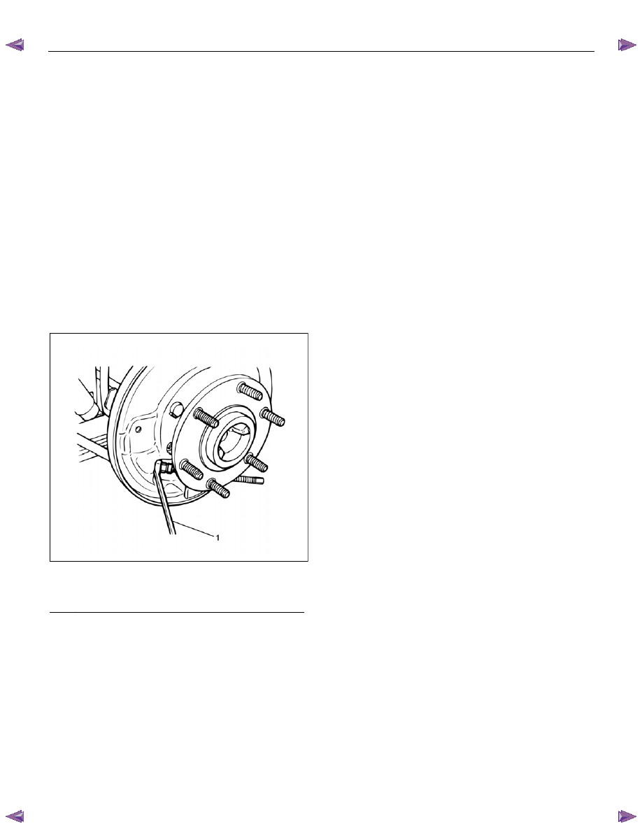
8. Use offset box wrench (12 mm hex.) to compress
locking lugs on the cable, then remove parking
brake outer cable from back plate.
NOTE: Do not twist or bend the cable too much.
A damaged cable will cause poor operation or a cable
break down.
RTW55CSH000301
Legend
(1) Offset Box Wrench (12 mm hex)
9. Remove nut to fix the cable on the leaf spring.
10. Take out parking brake rear cable from the back
plate.
11. Remove parking brake cable bolt and nut.
12. Disconnect T-end from the equalizer of front cable.
Installation
NOTE: Be sure to use a new shoe clamp spring and a
new adjuster lever clip.
1. Apply grease (multipurpose type grease) to the
connecting portion of the rear cable and equalizer.
(arrow mark).
2. Install parking brake outer cable in back plate and
inner cable in parking brake lever.
3. Install return spring.
4. Install shoe clamp spring and tension pin.
5. Install shoe assembly with adjuster lever, shoe
assembly with parking brake lever and spring. ----
snap action
6. Install nut and tighten it to the specified torque.
Torque: 7 N
⋅⋅⋅⋅m (0.7 kgf⋅⋅⋅⋅m/61 lb⋅⋅⋅⋅in)
7. Connect T-end with equalizer through outer cable
retainer.
8. Install parking brake cable nut and tighten it to the
specified torque.
Torque: 15 N
⋅⋅⋅⋅m (1.5 kgf⋅⋅⋅⋅m/11 lb⋅⋅⋅⋅ft)
9. Install parking brake cable bolt and tighten it to the
specified torque.
Torque: 7 N
⋅⋅⋅⋅m (0.7 kgf⋅⋅⋅⋅m/61 lb⋅⋅⋅⋅in)
10. Install brake drum.
11. Install wheel and tire.
12. Pull parking brake lever with a force equivalent to
operating force: 490 N (50 kg/110 lb), 10 times for
conditioning.
13. Adjust parking brake lever adjusting nut so that
parking brake lever goes through 6-9 notches
(Bucket Seat) or 8
−14 notches (Bench Seat), when
pulled with an operation force of 294 N (30 kg/
66 lb).
14. Check brake for no drag.
PARKING BRAKE SYSTEM 5D-11
Inspection and Repair
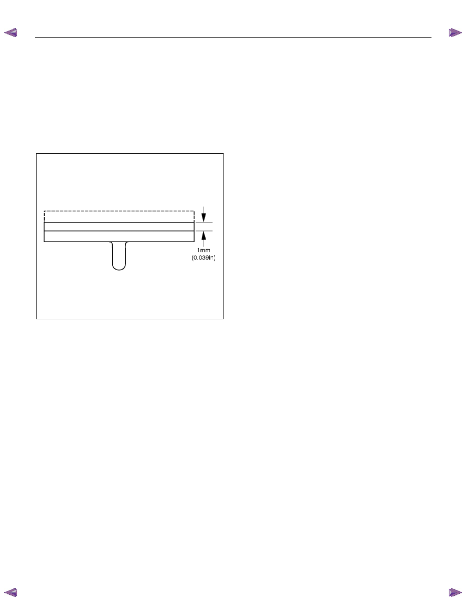
Brake Lining Inspection
Check the shoe assemblies for wear by removing the
brake drum.
Replace the shoe assemblies if the lining thickness is
less than 1.0 mm (0.039 in).
Minimum limit: 1.0 mm (0.039 in)
308RS004
Parking Brake Adjustment
NOTE: All brakes are self-adjusting. Brakes are
adjusted by repeated stepping on the brake pedal.
(After stepping on the pedal and releasing it, the rear
brake auto-adjuster produces a clicking sound. The
same operation should be repeated until the sound
disappears.)
Take the following steps after overhauling the rear
brake assembly.
1. Move the parking brake lever to its fully released
position.
2. Parking brake cable must be loosened sufficiently.
(Loosen the adjust nut.)
3. Repeat stepping on the brake pedal firmly, and
releasing it until the clicking sound can no longer
be heard.
If the difference between the brake drum inside
diameter and the brake shoes external diameter is
adjusted to be 0.4 mm (0.0157 in), the number of
times for depressing the brake pedal can be
reduced.
4. Remove the drum. Measure the brake drum inside
diameter and the brake shoes external diameter.
Total shoe clearance: 0.4 mm (0.0157 in)
If incorrect, readjust the brake shoe clearance.
5. Rotate the adjust nut of hand brake lever until all
slack disappears from the cable. Set the adjust
nut.
6. After the rear brake shoe/drum gap has been
adjusted, perform parking brake cable adjustment.
7. Turn the adjusting nut so that the parking brake
lever travels 6
−9 notches (Bucket Seat) or 8−14
notches (Bench Seat) when pulled up with a force
of 294 N (30 kg/66 lb).
8. Make sure there is no brake dragging.

5D-12 PARKING BRAKE SYSTEM
Main Data and Specifications
General Specifications
Type
Leading-Trailing
Drum inside diameter
254 mm (10 in) or 295 mm (11.6 in)
Parking brake lever stroke
6
−9 notches; Bucket Seat
8
−14 notches; Bench Seat
When pulled with a force of 294 N (30 kg/66 lb)
PARKING BRAKE SYSTEM 5D-13
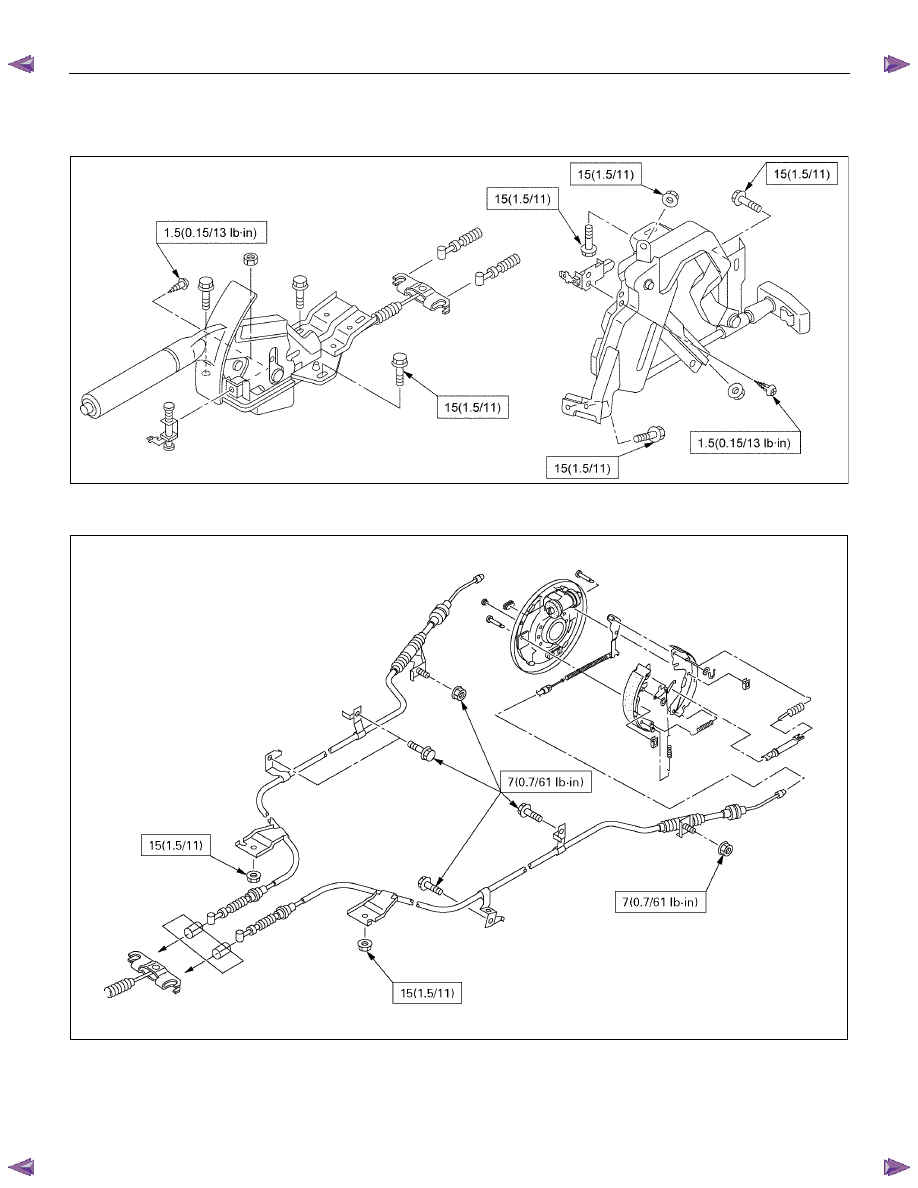
Torque Specifications
N
⋅⋅⋅⋅m (kgf⋅⋅⋅⋅m/lb⋅⋅⋅⋅ft)
This illustration is based on the RHD model
RTW35DSF000201
N
⋅⋅⋅⋅m (kgf⋅⋅⋅⋅m/lb⋅⋅⋅⋅ft)
E05R300006
Нет комментариевНе стесняйтесь поделиться с нами вашим ценным мнением.
Текст