Isuzu KB P190. Manual — part 635
Engine Mechanical – V6
Page 6A1–61
3.7
Accessory Drive Belt Tensioner
Assembly
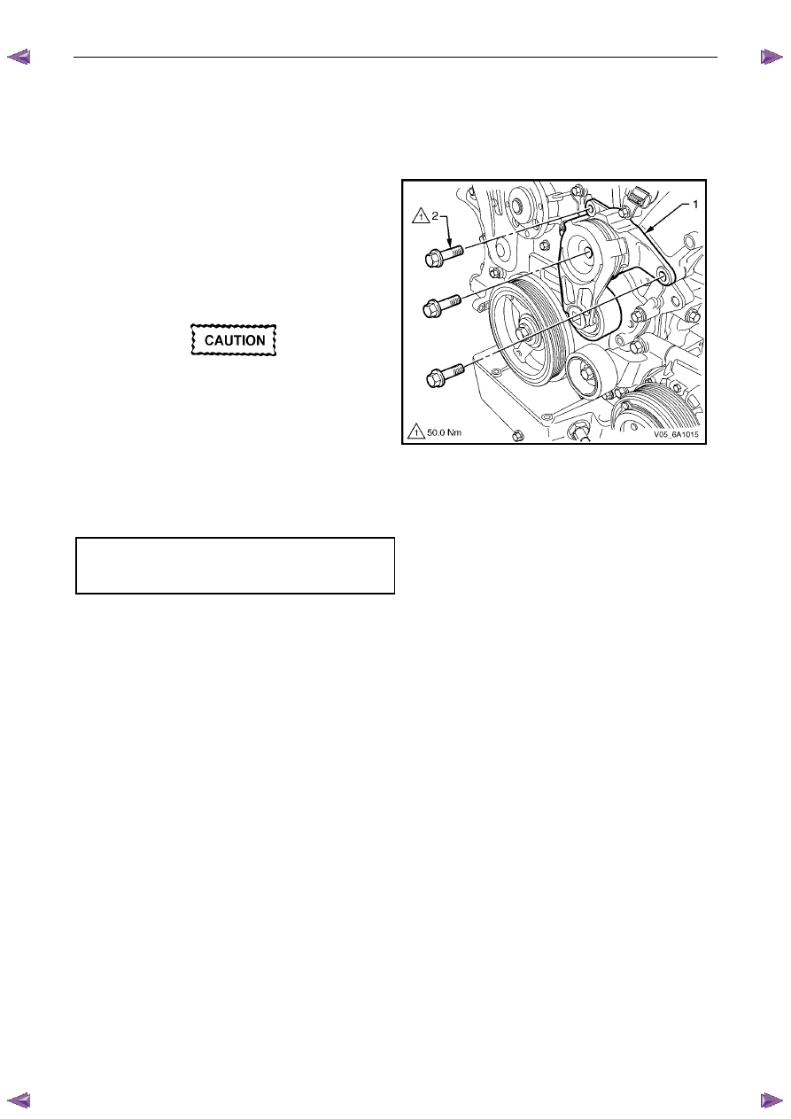
Remove
1
Remove the accessory drive belt, refer to 3.5
Accessory Drive Belt.
2
Remove the three bolts (2) attaching accessory drive
belt tensioner assembly (1).
3
Remove the accessory drive belt tensioner assembly.
N O T E
The accessory drive belt tensioner pulley is not
serviced separately. If the pulley is found to be
faulty, the entire tensioner assembly must be
replaced.
Repairing a damaged accessory drive belt
pulley should not be attempted under any
circumstances.
Figure 6A1 – 32
Reinstall
Reinstallation of the accessory drive belt tensioner assembly is the reverse of the removal procedure. Tighten the bolts to
the correct torque specification.
Accessory drive belt tensioner
attaching bolt torque specification. . . . . ..50.0 Nm
Engine Mechanical – V6
Page 6A1–62
3.8
Power Steering Pump Bracket
Remove
1
Remove the power steering pump and reservoir, refer to 3B_Steering.
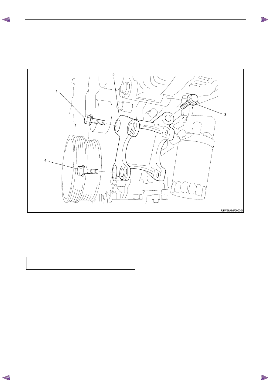
2
Remove the three bolts (1), (3) and (4) attaching the power steering pump bracket (5) to the engine block.
3
Remove the power steering pump bracket.
Figure 6A1 – 33
Reinstall
Reinstallation of the power steering pump and pump bracket is the reverse of the removal procedure, noting the
following:
1
Hand start the bolts before tightening.
2
Tighten the bolts to the correct torque specification.
Power steering pump bracket
attaching bolt torque specification. . . . . ..22.0 Nm
3.9
Upper Intake Manifold
The intake manifold comprises of an upper and lower section. Some service procedures only require the removal of the
upper intake manifold (e.g. fuel injector/spark plug servicing), while other service procedures require the removal of both
the upper and lower manifold as a complete assembly (e.g. cylinder head/s). If the complete assembly needs to be
removed, refer to 3.10
Intake Manifold Assembly – Complete.
Engine Mechanical – V6
Page 6A1–63
Remove
Disconnection of the battery affects certain
vehicle electronic systems. Refer to 1.1
WARNING, CAUTION and NOTES before
disconnecting the battery.
1
Disconnect the battery negative terminal.
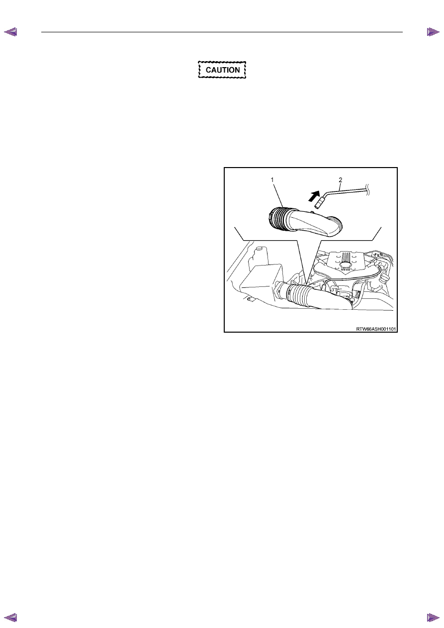
2
Remove the air intake duct (1) and hose (2), refer to
6C1-3 Engine Management – V6 – Service
Operations.
Figure 6A1 – 34
Engine Mechanical – V6
Page 6A1–64
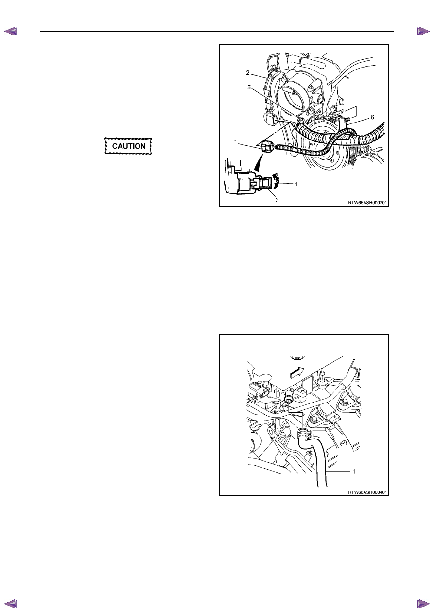
3
Retract the throttle body wiring connector lock (3).
4
While pressing the connector latch in the direction of
the arrow (4), disconnect the throttle body wiring
connector.
5
Disconnect the throttle body connector wiring harness
from its retaining clip (5).
6
Remove the main wiring harness retainer pin (6) from
the intake manifold by pushing from the front to the
rear using a suitable piece of 5 mm steel rod (or an
Allen key).
The following precautions must be followed
when disconnecting the throttle body wiring
connector:
•
Do not use any mechanical device such
as a screwdriver to disengage the
harness connector (1) from the throttle
body (2).
•
When retracting the throttle wiring
connector lock (3), take care not to
disengage the lock from the connector.
•
Do not pull on the connector wires.
•
Take care not to break the barbed
harness retainer pin (6) while removing
the harness retainer from the intake
manifold.
•
Should the pin be broken, then it is
vital that a new harness retainer is
fitted to the wiring harness shield. If
not, the harness will foul the engine
drive belt.
Figure 6A1 – 35
7
Disconnect the brake booster hoses from the upper
intake manifold:
Figure 6A1 – 36
Нет комментариевНе стесняйтесь поделиться с нами вашим ценным мнением.
Текст