Isuzu KB P190. Manual — part 29
1-82 HEATER AND AIR CONDITIONING
RTW710SH000801
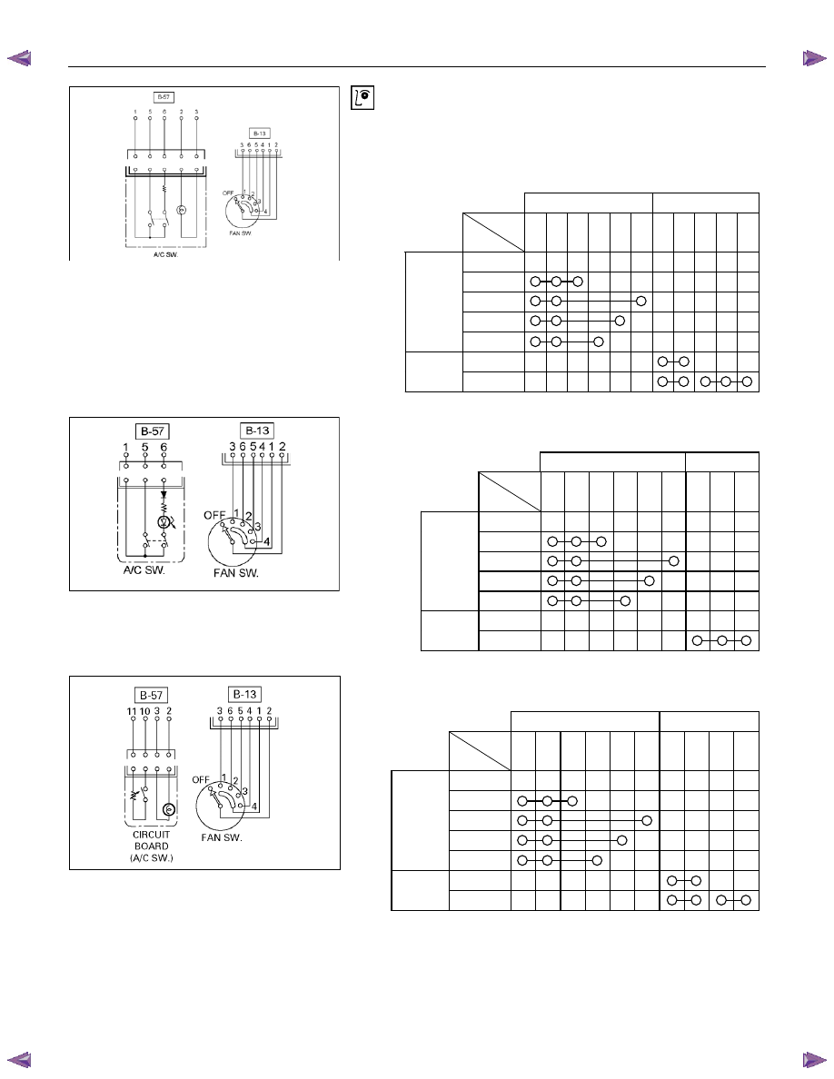
Fan switch and A/C switch
Check for continuity between fan switch and A/C switch side
connector terminals.
(A/C (4JA1-T, 4JJ1-TC Standard Output, 4JJ1-TC High
Output, 4JK1-TC High Output))
B-13 B-57
Terminal
No.
SW.
position
1
2
3
4
5
6
2
3
1
5
6
OFF
1
2
3
(FAN SW.)
4
OFF
(A/C SW.)
ON
RUW710SH000501
(A/C (4JH1-TC, C24SE)).
B-13 B-57
Terminal
No.
SW.
position
1
2
3
4
5
6
1
5
6
OFF
1
2
3
(FAN SW.)
4
OFF
(A/C SW.)
ON
D08R300070
(Cooler)
B-13 B-57
Terminal
No.
SW.
position
1
2
3
4 5 6 2
3
10
11
OFF
1
2
3
(FAN SW.)
4
OFF
(A/C SW.)
ON

HEATER AND AIR CONDITIONING 1-83
RTW410SH000201
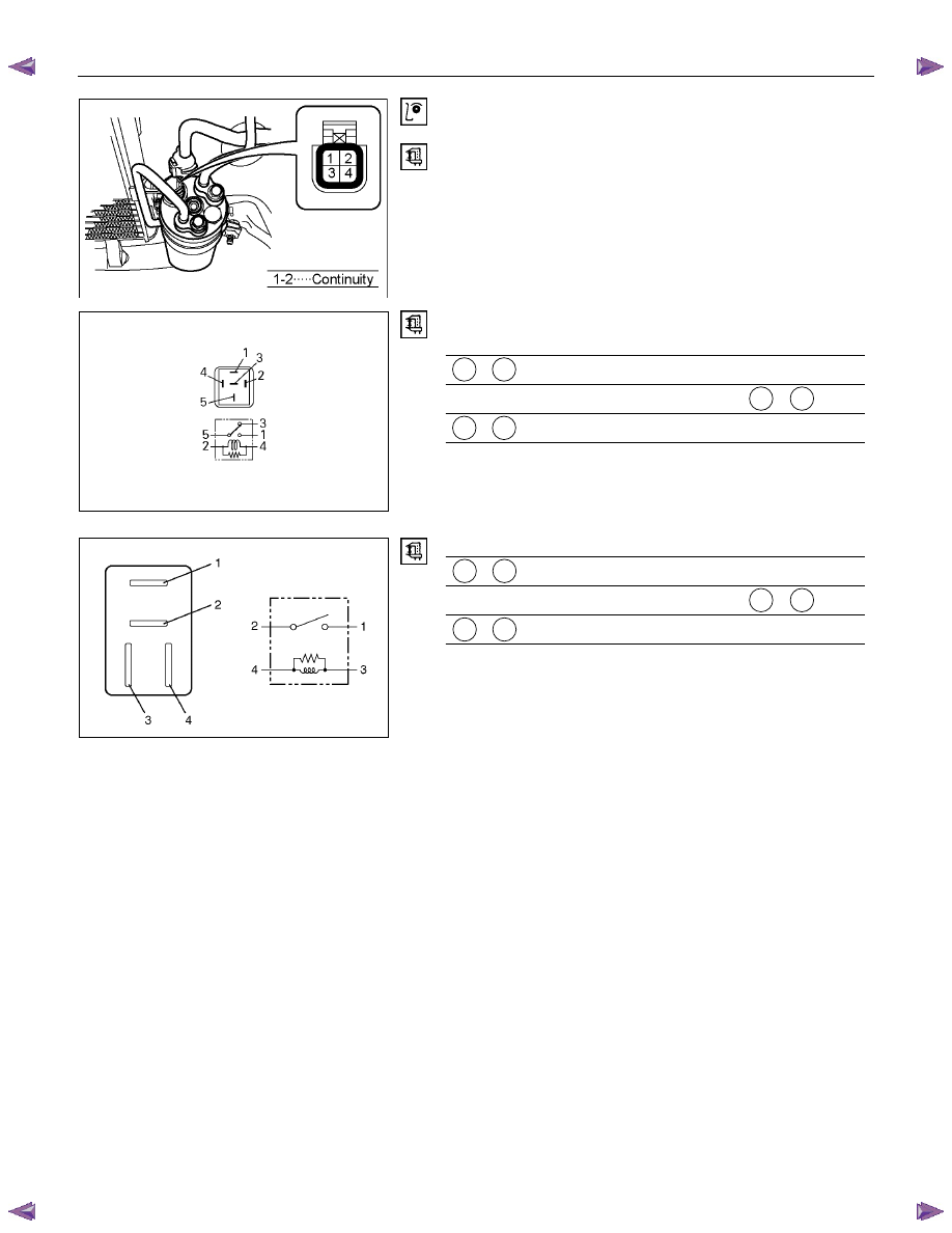
Electronic thermostat
Check for continuity between electronic thermostat side
connector terminals.
(A/C)
(Cooler)
1-84 HEATER AND AIR CONDITIONING
RTW4A0SH000201
Triple Pressure switch
Disconnect pressure switch connector and check for continuity
between pressure switch side connector terminal.
825r300045
Heater and thermo switch relay.
Check for continuity between the relay terminals.
1 - 5 ⋅⋅⋅⋅⋅ No continuity
(When battery voltage is applied between 2 - 4 )
1 - 5
⋅⋅⋅⋅⋅ Continuity
825r300023
Check for continuity between the relay terminals.
1 - 2 ⋅⋅⋅⋅⋅ No continuity
(When battery voltage is applied between 3 - 4 )
1 - 2
⋅⋅⋅⋅⋅ Continuity
HEATER AND AIR CONDITIONING 1-85
TROUBLESHOOTING
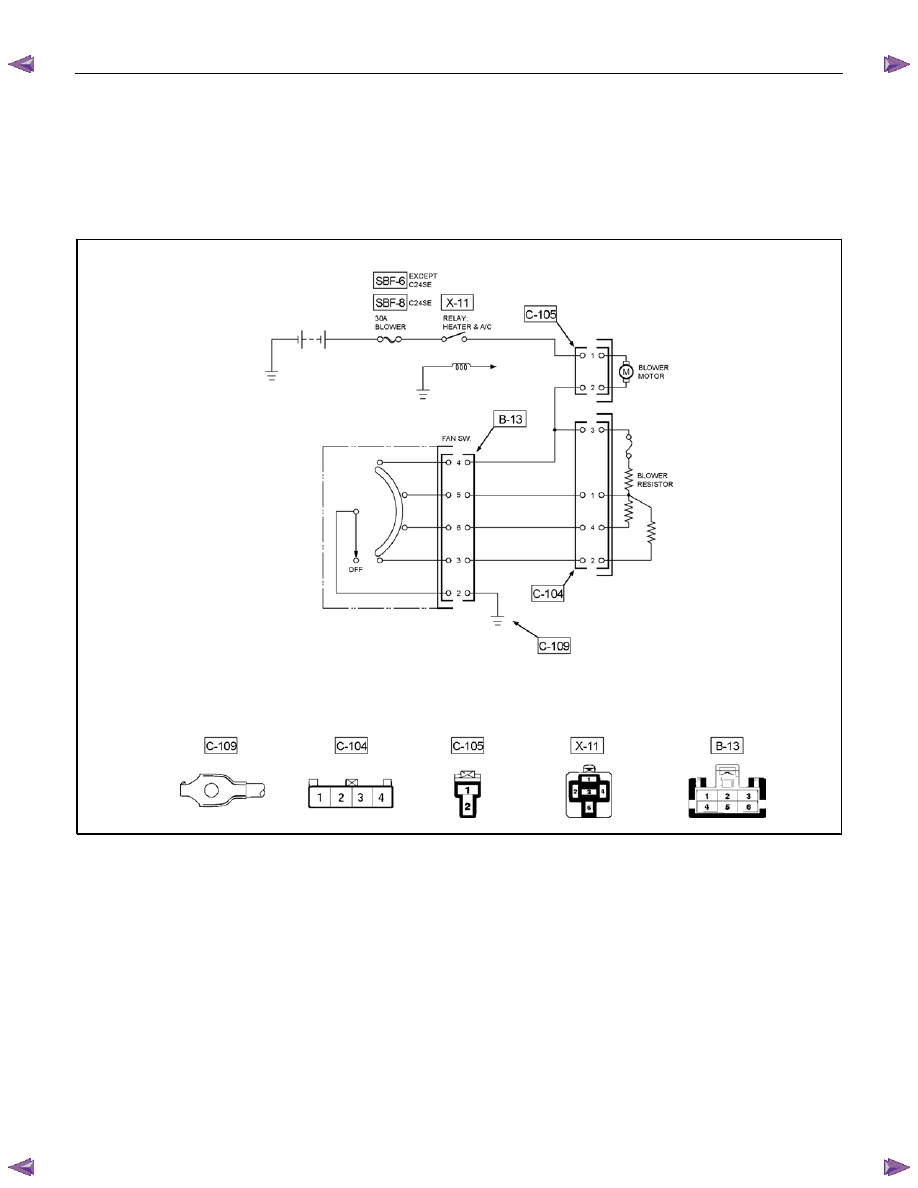
FAN CONTROL KNOB (FAN SWITCH)
Current flows to the blower motor through the Heater & A/C relay (X-11) to activate the rotation of the blower motor
by turning “ON” the fan control knob (fan switch). Blower motor speed is controlled in stages by the resistor, by
operating the switch from “LOW” to “HIGH.”
RTW710LF004201
Нет комментариевНе стесняйтесь поделиться с нами вашим ценным мнением.
Текст