Isuzu KB P190. Manual — part 1191
Manual Transmission (MUX) 7B1-45
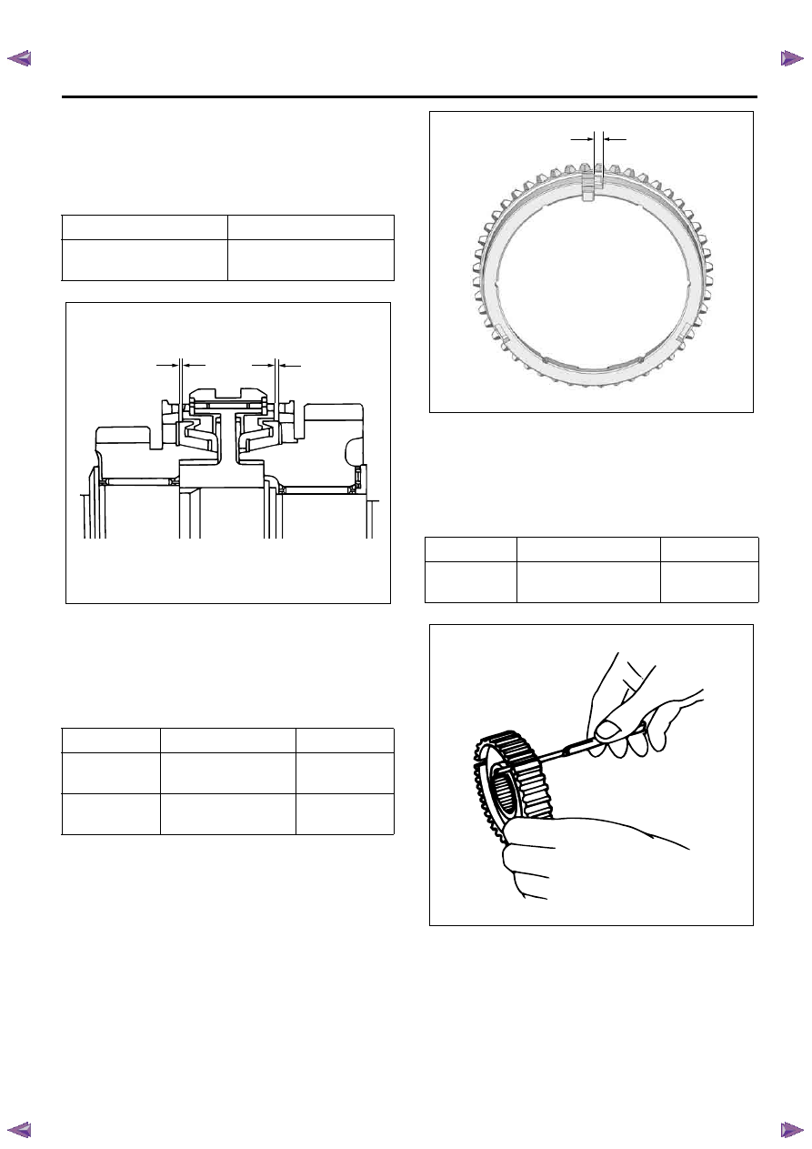
1st-2nd Synchronizer (3-CONE)
Use a thickness gauge to measure the clearance
between the block ring and the dog teeth.
If the measured value exceeds the specified limit, the
1st-2nd synchronizer assembly must be replaced.
Block Ring and Insert Clearance
Use a vernier caliper or thickness gauge to measure
the clearance between the block ring and insert.
If the measured value exceeds the specified limit, the
block ring and insert must be replaced.
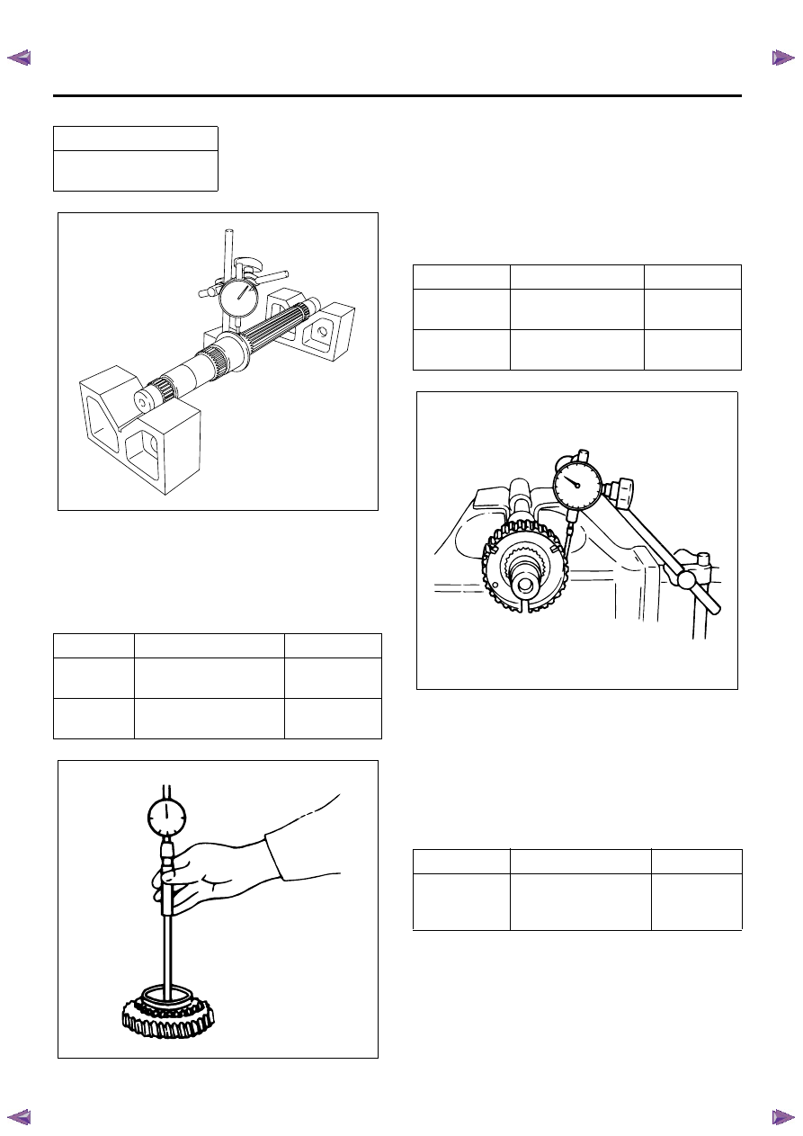
Clutch Hub and Insert Clearance
Use a thickness gauge to measure the clearance
between the clutch hub and insert.
If the measured value exceeds the specified limit, the
clutch hub and insert must be replaced.
Counter Shaft Run-out
• Install the counter shaft to V-blocks.
• Use a dial indicator to measure the counter shaft
central portion run-out.
If the measured counter shaft run-out exceeds the
specified limit, the counter shaft must be replaced.
Standard
Limit
1.5 mm
(0.059 in)
0.8 mm
(0.031 in)
Standard
Limit
1st - 2nd
3.86 - 4.16 mm
(0.152 - 0.164 in)
4.4 mm
(0.173 in)
Reverse
2.16 - 2.46 mm
(0.085 - 0.097 in)
2.7 mm
(0.106 in)
LNW25CSH028501
Standard
Limit
1st - 2nd
Reverse
0.01 - 0.21 mm
(0.0004 - 0.0083 in)
0.3 mm
(0.0118 in)
RTW77BSH006501
LNW25CSH028701
7B1-46 Manual Transmission (MUX)
Gear Inside Diameter
Use an inside dial indicator to measure the gear inside
diameter.
If the measured value is less than the specified limit,
the gear must be replaced.
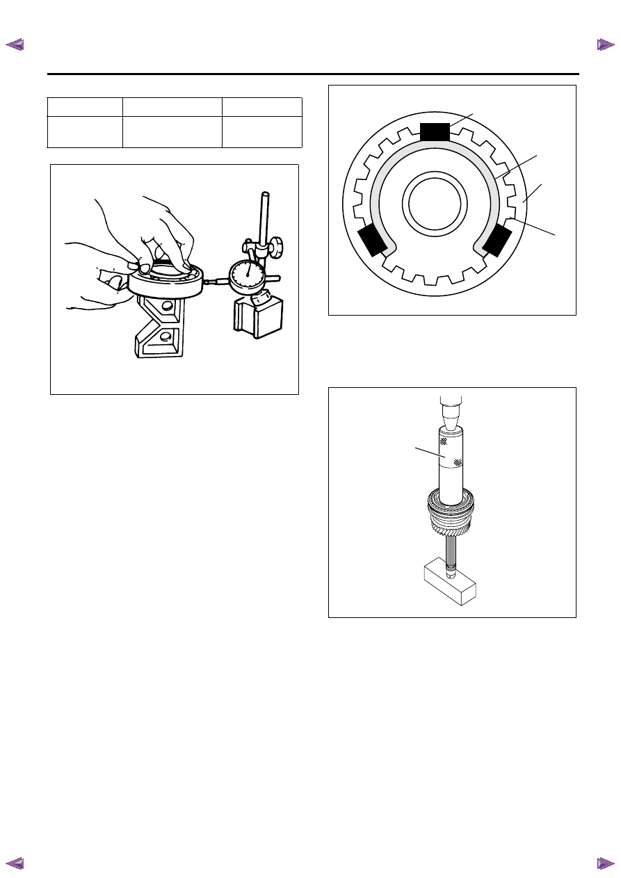
Clutch Hub Spline Play
• Set a dial indicator to the clutch hub to be
measured.
• Move the clutch hub as far as possible to both the
right and the left.
Note the dial indicator reading.
If the measured value exceeds the specified limit, the
clutch hub must be replaced.
Counter Gear Spline Play
• Set a dial indicator to the gear to be measured.
• Move the gear as far as possible to both the right
and the left.
Note the dial indicator reading.
If the measured value exceeds the specified limit, the
gear must be replaced.
Ball Bearing Play
Use a dial indicator to measure the ball bearing play.
If the measured value exceeds the specified limit, the
ball bearing must be replaced.
Limit
0.05 mm
(0.002 in)
Standard
Limit
1st
2nd
53.000 - 53.019 mm
(2.0866 - 2.0874 in)
53.059 mm
(2.0889 in)
Reverse
42.000 - 42.019 mm
(1.6535 - 1.6543 in)
42.059 mm
(1.6559 in)
RTW77BSH002401
LNW25CSH028901
Standard
Limit
1st - 2nd
0 - 0.04 mm
(0 - 0.0016 in)
0.10 mm
(0.0039 in)
Reverse
0 - 0.107 mm
(0 - 0.0042 in)
0.15 mm
(0.0059 in)
Standard
Limit
3rd
5th
Output
0.013 - 0.121 mm
(0.0005 - 0.0048 in)
0.15 mm
(0.0059 in)
LNW25CSH029101
Manual Transmission (MUX) 7B1-47
Installation
1. Install the needle bearing, 2nd counter gear
assembly, 2nd inside ring, 2nd outside ring, and
2nd block ring.
• Apply engine oil to the needle bearing and gear
internal surface.
2. Assemble the 1st-2nd synchronizer assembly by
performing the following steps.
• Check that the inserts (1) fit snugly into the
clutch hub (4) insert grooves.
• Check that the inserts springs (2) are fitted to
the inserts as shown in the figure.
• Check that the clutch hub (4) and sleeve (3)
slide smoothly.
• The insert springs (2) must be set in such a way
that the opening of each spring faces different
direction.
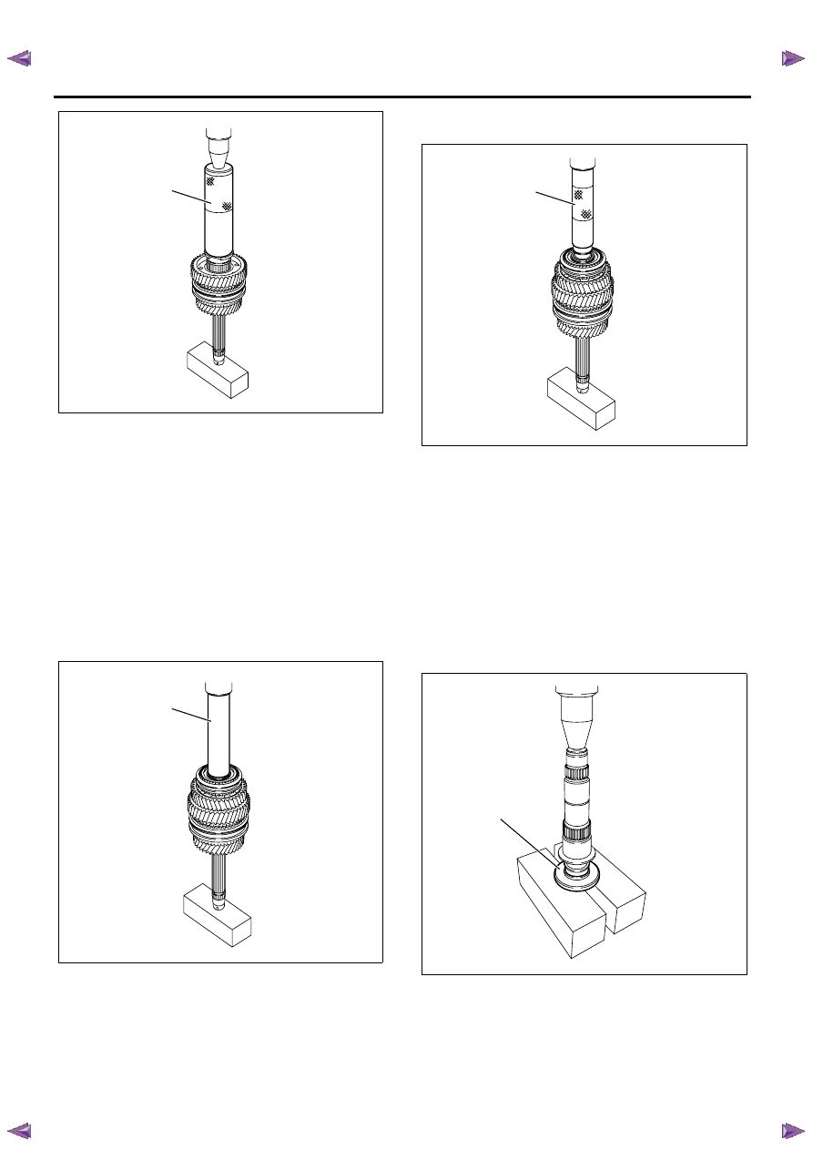
3. Use a bench press and installer 9-8522-1182-0 (1)
to install the 1st-2nd synchronizer assembly, 1st
block ring, 1st outside ring and 1st inside ring.
• Apply engine oil to the block ring internal
surface.
4. Install the needle bearing and 1st counter gear
assembly.
• Apply engine oil to the needle bearing and gear
internal surface.
5. Use a bench press and installer 9-8522-1182-0 (1)
to install the 1st counter collar.
Notice:
The collar must be press fitted with end surface of
sleeve & hub.
Standard
Limit
Front
0 - 0.098 mm
(0 - 0.0039 in)
0.15 mm
(0.0059 in)
LNW25CSH029201
LNW45CSH002301
1
2
3
4
RTW75CSH000901
1
7B1-48 Manual Transmission (MUX)
6. Install the new 1st counter snap ring.
• Never reinstall the used snap ring.
Notice:
The snap ring must be assembled in groove surely.
7. Install the needle bearing, reverse block ring, and
reverse counter gear assembly.
• Apply engine oil to the needle bearing and gear
internal surface.
8. Use a bench press and installer 5-8840-2244-0 (1)
to install the reverse synchronizer assembly.
• Apply engine oil to the block ring internal
surface.
9. Use a bench press and installer 5-8840-2346-0 (1)
to install the counter front roller bearing inner race.
10. Install the counter front roller bearing outer race.
11. Use a pair of snap ring pliers to install the new
reverse counter snap ring.
• Never reinstall the used snap ring.
Notice:
The snap ring must be assembled in groove surely.
12. Install the counter middle roller bearing by
performing the following steps.
a. Use a bench press and installer 5-8840-2847-0
(1) to install the counter middle roller bearing
inner race.
b. Install the counter middle roller bearing outer
race.
Notice:
• Direction of assembling exists. (Flange of inner race
to be shaft side.)
RTW75CSH001001
1
RTW75CSH001101
1
RTW75CSH000801
1
RTW77BSH002501
1
Нет комментариевНе стесняйтесь поделиться с нами вашим ценным мнением.
Текст