Isuzu KB P190. Manual — part 212
ENGINE MECHANICAL 6A – 43
ENGINE OVERHAUL
REMOVAL
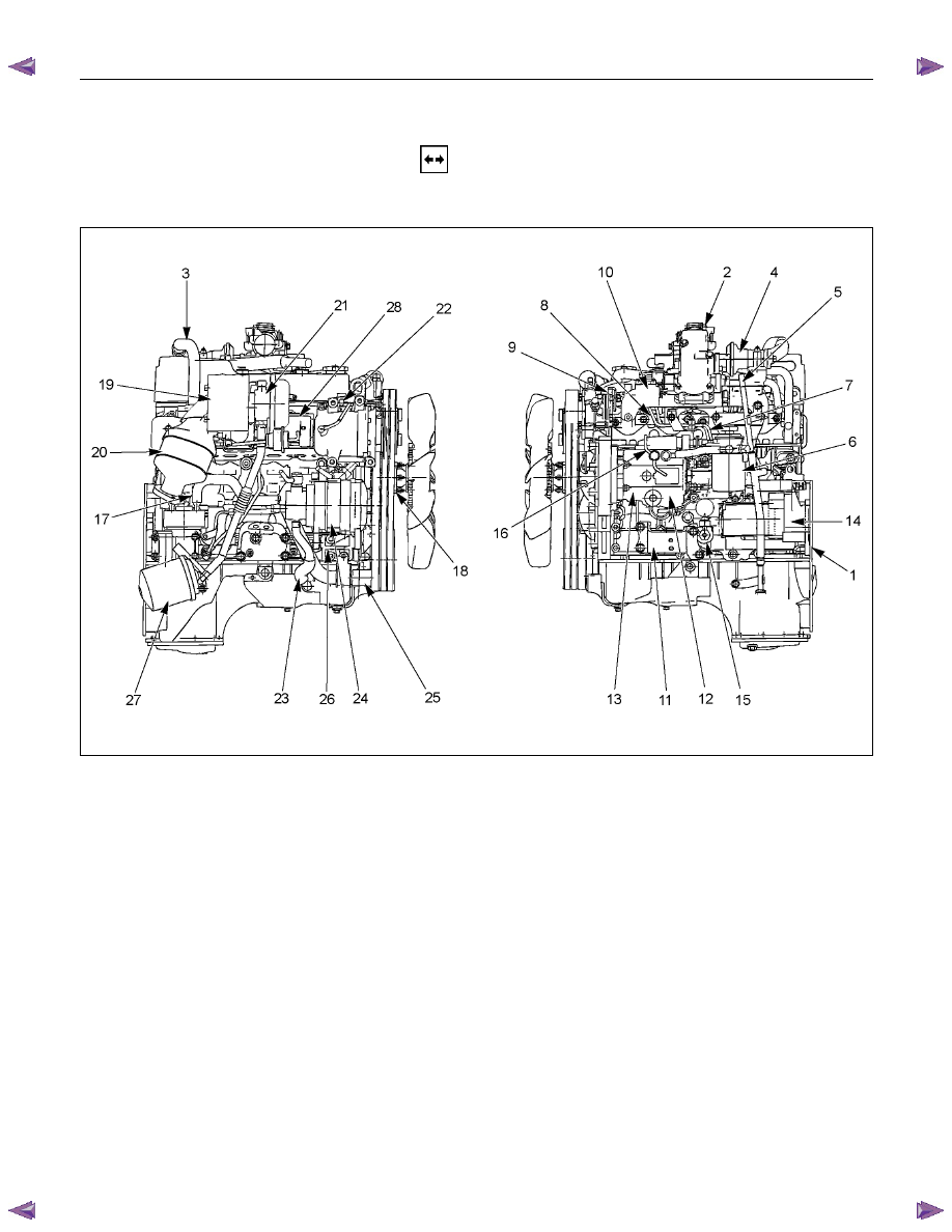
EXTERNAL PARTS
RTW36AMF000401
Removal Steps
1. Clutch Assembly or Flex Plate
2. Intake Pipe and Throttle Body
3-1. EGR Pipe
3-2. EGR cooler (EURO III model only)
4. EGR Valve
5. Oil Level Gauge
6. Fuel Filter Assembly (Except EURO III)
7. Fuel Filter Bracket (Except EURO III)
8. Fuel Injection Pipe with Clip
9. Power Steering Oil Pump Bracket
10. Intake Manifold
11. Engine Mounting Bracket and Foot
12. Injection Pump Cover
13. Injection Pump
14. Starter Motor
15. Oil Pressure Warning Switch
16. Fuel Leak Off Pipe
17. Oil Cooler Water Pipe
18. Cooling Fan Pulley
19. Heat Protector
20. Catalytic Converter
21.
Turbocharger
22. Compressor Bracket
23. Vacuum Pump Oil Return Hose
24. Generator and Adjusting Plate
25. Water Inlet Pipe
26. Generator Bracket
27. Oil Cooler with Oil Filter
28. Exhaust Manifold
6A – 44 ENGINE MECHANICAL
Removal
1. Clutch Assembly or Flex Plate
Remove the clutch assembly or the flex plate.
4JA1L
RTW46ASH000801
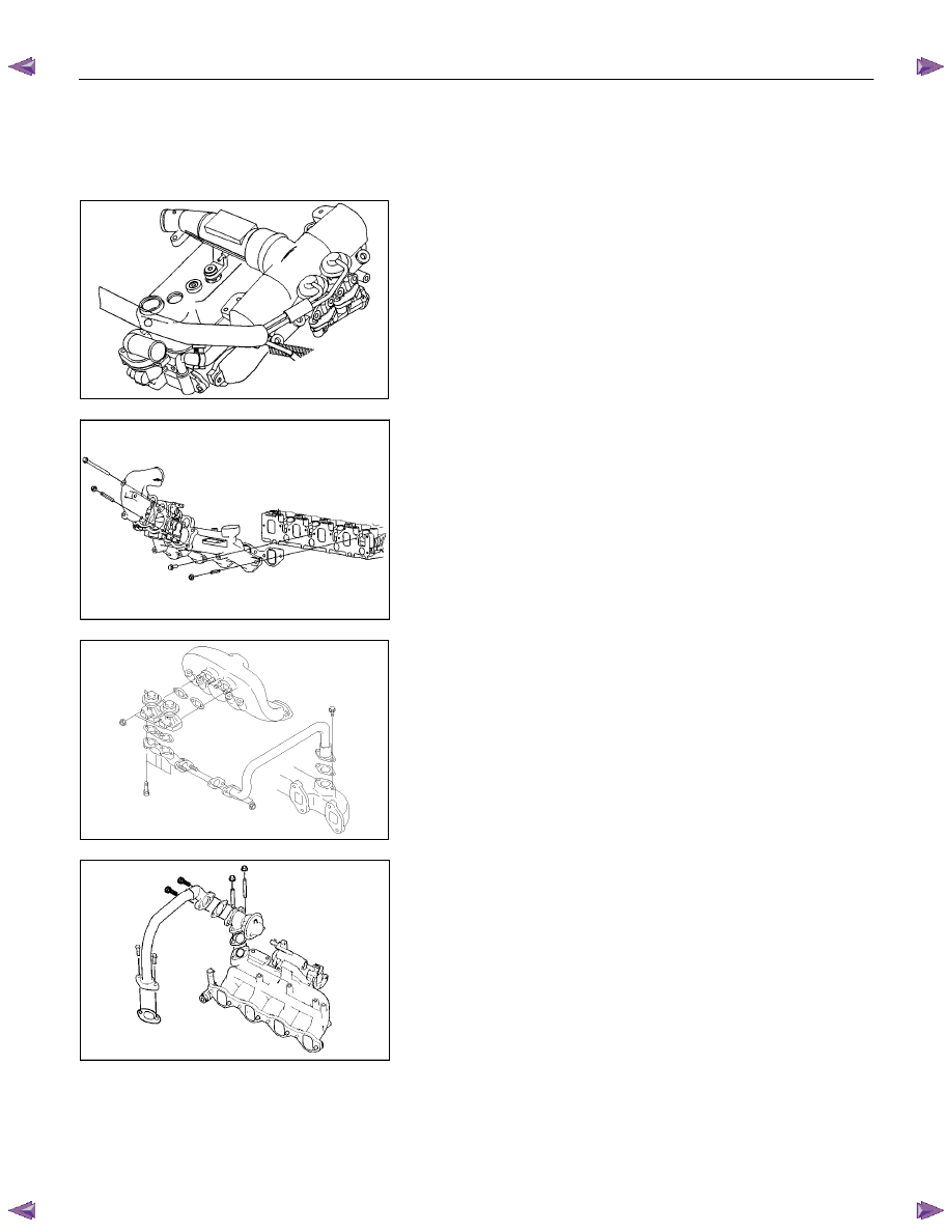
2. Intake Pipe and Throttle Body (4JA1TC/4JH1TC only)
1) Loosen hose clamp between turbocharger and intake
duct.
2) Remove the rubber hose.
3) Remove the intake pipe and the throttle body.
(4JA1TC/4JH1TC only)
RTW36ASH000201
4JA1L
025R100008
3-1. EGR Pipe
1) Remove two bolts from the exhaust manifold.
2) Remove two nuts from the EGR valve adapter.
3) Remove the EGR pipe with gaskets.
RTW36ASH000301
3-2. EGR Cooler (EURO III model only)
4JA1TC/4JH1TC
4JH1TC
ENGINE MECHANICAL 6A – 45
4JA1L
RTW46ASH001001
4. EGR
Valve
1) Remove four nuts and remove the EGR valve
assembly from the intake manifold.
2) Remove four bolts and remove the adapter from the
EGR valve assembly.
4JA1TC
RTW46ASH000901
5. Oil Level Gauge
1) Disconnect PCV hose.
2) Remove two bolts and remove the engine oil level
gauge.
6. Fuel Filter Assembly (Except EURO III model)
1) Disconnect fuel hose.
2) Remove two bolts and remove the fuel filter.
7. Fuel Filter Bracket (Except EURO III model)
Remove three bolts and remove the fuel filter bracket with
leak pipe.
4JH1TC
RTW36ASH001201
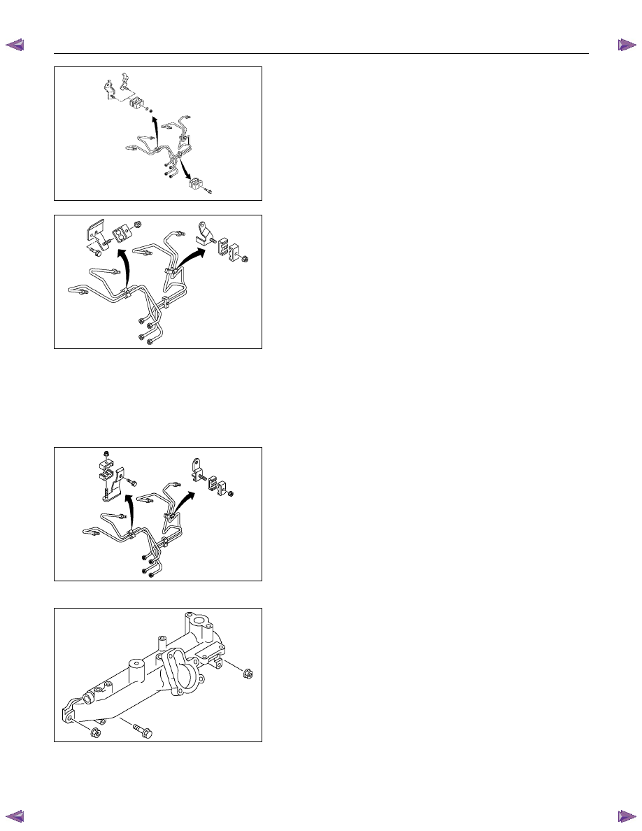
8. Fuel Injection Pipe with Clip
1) Loosen the injection pipe sleeve nuts at pump side
and nozzle side.
Do not apply excessive force to the injection pipes.
2) Loosen the injection pipe clips.
3) Remove the injection pipe.
NOTE:
Plug the delivery holder ports with the caps to prevent the
entry of foreign material.
9. Power Steering Oil Pump Bracket
RTW36ASH000701
10. Intake Manifold
1) Disconnect the PCV hose from the cylinder head
cover.
2) Remove the intake manifold with gasket.
11. Engine Mounting Bracket and Foot
12. Injection Pump Cover

6A – 46 ENGINE MECHANICAL
13. Injection Pump
Refer to section 6C-19 (Injection Pump)
14. Starter Motor
15. Oil Pressure Warning Switch
16. Fuel Leak Off Pipe
17. Oil Cooler Water Pipe
18. Cooling Fan Pulley
19. Heat Protector
20. Catalytic Converter
21. Turbocharger
1) Disconnect the water hose between thermostat
housing cover and turbocharger.
2) Disconnect the water hose between water inlet pipe
and turbocharger.
3) Remove the oil feed pipe.
4) Remove the oil return pipe.
5) Remove the turbocharger and the gasket.
NOTE:
Plug the turbocharger body oil ports and water ports after
removing the turbocharger assembly to prevent the entry
of foreign material.
22. Compressor Bracket
23. Vacuum Pump Oil Return Hose
24. Generator and Adjusting Plate
25. Water Inlet Pipe
26. Generator Bracket
27. Oil Cooler with Oil Filter
28. Exhaust Manifold
027R100007
037RY00001
Нет комментариевНе стесняйтесь поделиться с нами вашим ценным мнением.
Текст