Isuzu KB P190. Manual — part 762
Engine Mechanical – V6
Page 6A1–271
Page 6A1–271
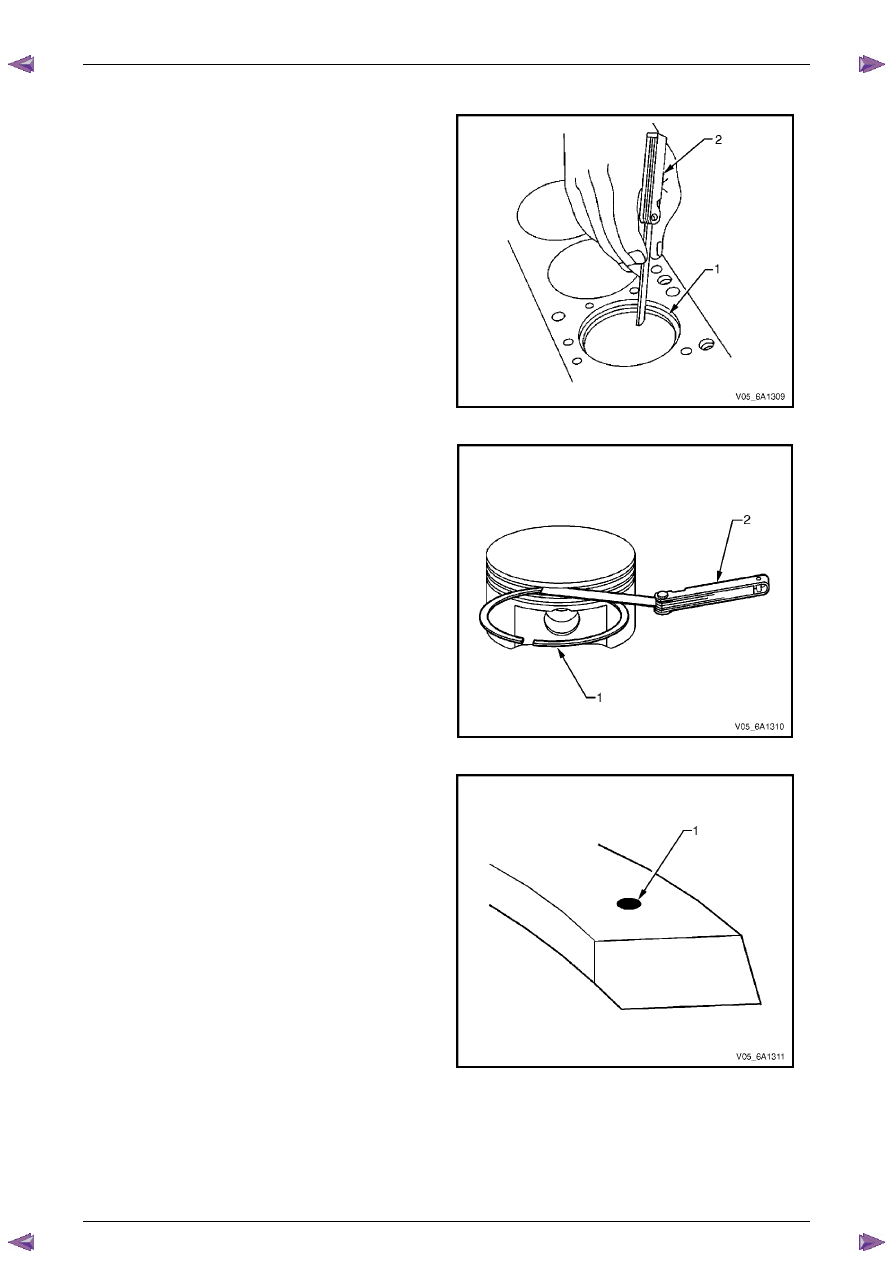
Piston Ring Measurement
1
Measure the piston ring end gap using the following
procedure:
a
Place the piston ring (1) in the area of the bore where
the piston ring will travel, approximately 25 mm below
the deck surface. Ensure the ring is square with the
cylinder bore by positioning the ring with the piston
head.
b
Measure the end gap of the piston ring with feeler
gauges (2), refer to
5 Specifications
.
c
If the clearance exceeds the provided specifications,
the piston rings must be replaced.
d
Repeat the procedure for all piston rings.
Figure 6A1 – 478
2
Measure the piston ring side clearance using the
following procedure:
a
Roll the piston ring (1) entirely around the piston ring
groove. If any binding is caused by the ring groove,
dress the groove with a fine file. If any binding is
caused by a distorted piston ring, replace the ring.
b
With the piston ring on the piston, use feeler
gauges (2) to check clearance at multiple locations.
c
Compare the measurements with piston ring side
clearance listed in the specifications, refer to
5 Specifications
.
d
If the clearance is greater than specifications, replace
the piston rings.
Figure 6A1 – 479
3
There is a locating dimple (1) on the compression
rings. Install the compression rings with the dimple
facing up.
4
If the new ring does not reduce the clearance to the
correct specification, install a new piston.
5
If the new piston does not meet clearance
specifications, the cylinder block may need to be
oversized to 0.25 mm. There is only one size of
oversized pistons and rings available for service.
Figure 6A1 – 480
Engine Mechanical – V6
Page 6A1–272
Page 6A1–272
Connecting Rod Cleaning Procedure
1
Clean the connecting rods in solvent.
Safety glasses must be worn when using
compressed air.
2
Dry the connecting rod using compressed air.
3
Remove the connecting rod cap and clean the threads.
4
Remove the connecting rod bearing and discard. Never reuse a connecting rod bearing that has been used in a
running engine.
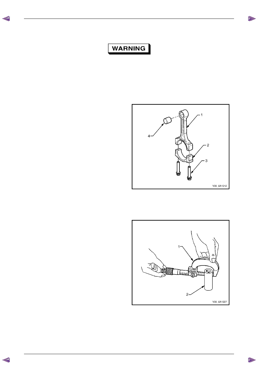
Connecting Rod Visual Inspection Procedure
1
Inspect the piston pin bushing (4) for scoring or
damage.
2
Inspect the connecting rod beam (1) for twisting or
bending.
3
Inspect the rod cap (2) for any nicks or damage
caused by possible interference.
4
Inspect for scratches or abrasion on the rod bearing
seating surface.
5
If the connecting rod bores contain minor scratches or
abrasions, clean the bores in a circular direction with
a light emery paper.
6
Retain the original bolts (3) for preliminary assembly.
They must be replaced for final assembly.
Figure 6A1 – 481
Connecting Rod Measurement Procedure
Piston Pin End
N O T E
Measurements of all components should be
taken with the components at normal room
temperature.
1
Using an outside micrometer (1), take two
measurements of the piston pin (2) in the area of the
connecting rod contact.
Figure 6A1 – 482
Engine Mechanical – V6
Page 6A1–273
Page 6A1–273
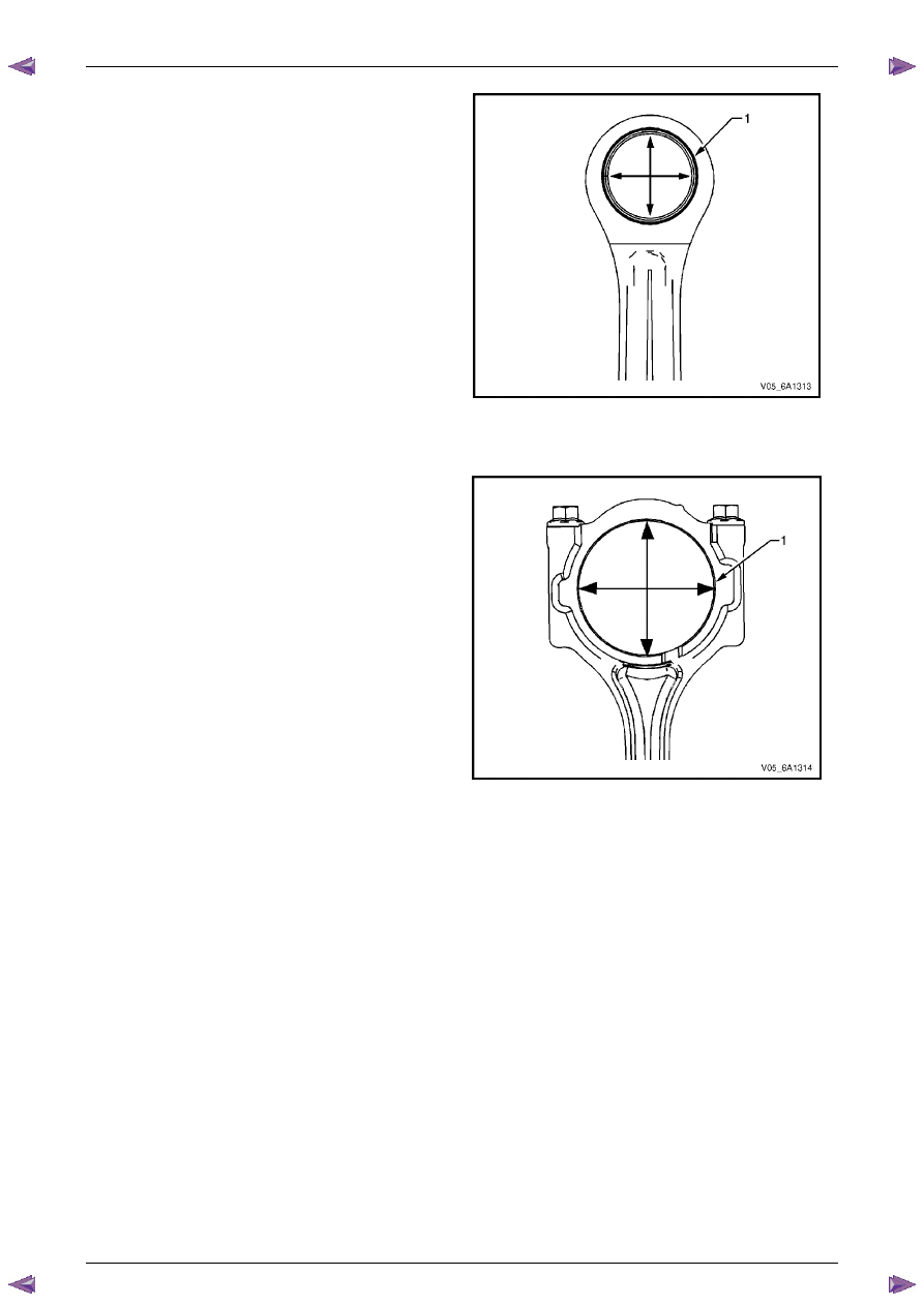
2
Using an inside micrometer, measure the connecting
rod piston pin bore (1).
3
Subtract the piston pin diameter from the piston pin
bore.
4
Compare the clearance measurements listed in the
specifications, refer to
5 Specifications
.
5
If the clearance is excessive, replace the piston pin. If
a new pin does not resolve the clearance problem,
replace the connecting rod.
Figure 6A1 – 483
Crankshaft Bearing End
N O T E
Measurements of all components should be
taken with the components at normal room
temperature.
1
Using an inside micrometer, measure the connecting
rod crankshaft bearing bore (1).
2
Compare the bore measurements listed in the
specifications, refer to
5 Specifications
.
3
Replace the connecting rod if the bore is out of
specification. Do not recondition the connecting rod.
Figure 6A1 – 484
Engine Mechanical – V6
Page 6A1–274
Page 6A1–274
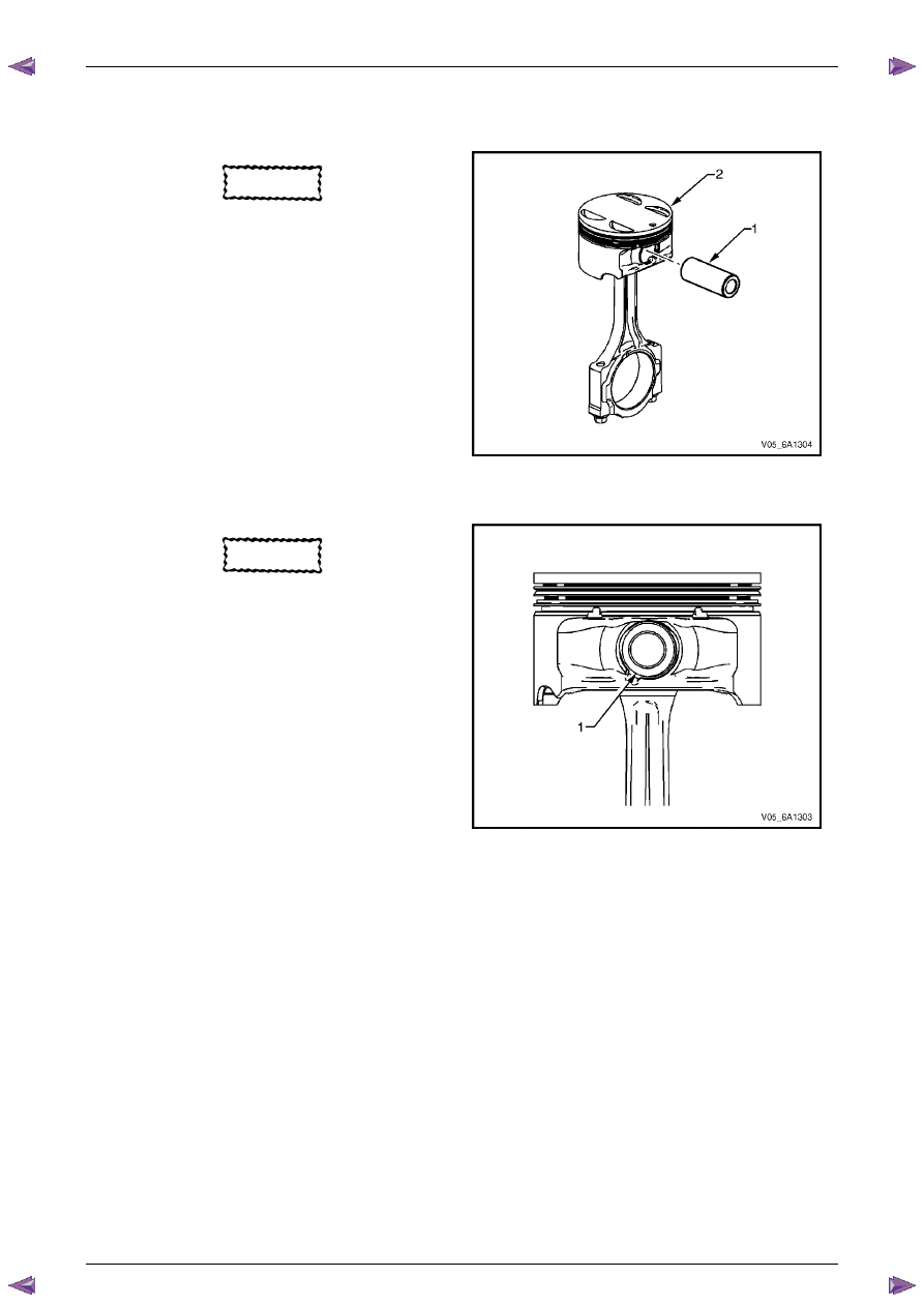
Reassemble
Piston and Piston Pin
CAUTION
The arrow located on top of the piston must
point toward the front of the engine.
N O T E
The connecting rod is non-directional and may
be assembled/reassembled to the piston in
either direction.
1
Lubricate the piston pin (1) bores in the piston (2) and
the connecting rod with clean engine oil.
2
Assemble the piston and piston pin to the connecting
rod. Correctly orient the piston when reusing a
marked connecting rod.
3
Align the piston pin bore with the connecting rod pin
bore.
4
Slide the piston pin into the piston and the connecting
rod.
Figure 6A1 – 485
CAUTION
New piston pin retainers must be used.
Never reuse the piston pin retainers.
5
Install new piston pin retainers (1).
6
Ensure the piston pin retainers are fully seated in their
grooves.
7
Repeat steps 1 to 6 for the remaining pistons.
Figure 6A1 – 486
Нет комментариевНе стесняйтесь поделиться с нами вашим ценным мнением.
Текст