Isuzu KB P190. Manual — part 761
Engine Mechanical – V6
Page 6A1–267
Page 6A1–267
CAUTION
Do not damage the crankshaft journal,
cylinder wall and piston cooling jets when
removing the connecting rod and piston
assembly.
12
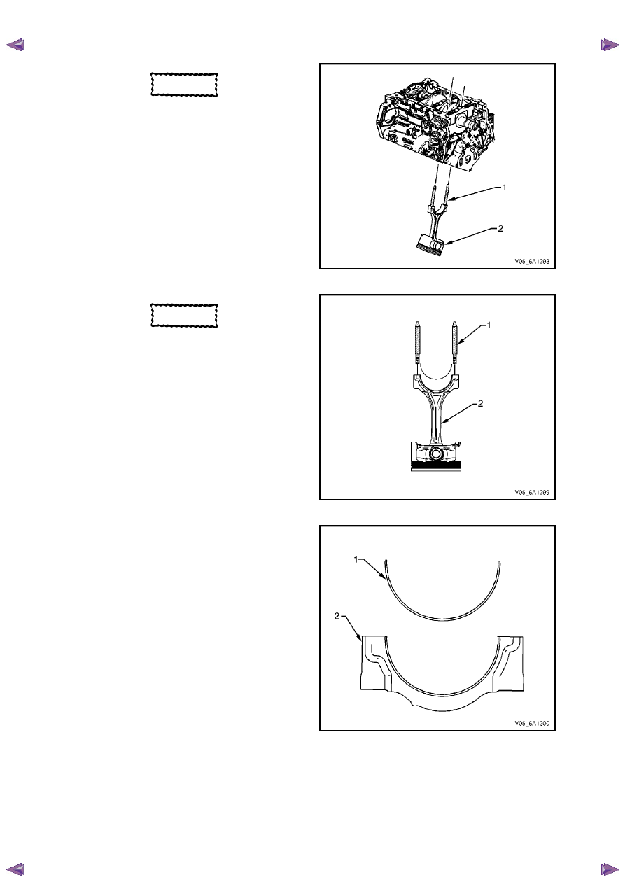
Using connecting rod guide pin set, Tool No.
EN-46121 (1), push the connecting rod and piston
assembly (2) through the top of the cylinder.
Figure 6A1 – 467
CAUTION
When dismantled, ensure the connecting
rod, connecting rod cap, piston and
bearings are organised in their original
position and location. This will also aid
engine mechanical diagnosis.
13
Remove connecting rod guide pin set, Tool No.
EN-46121 (1) from the connecting rod bolt holes.
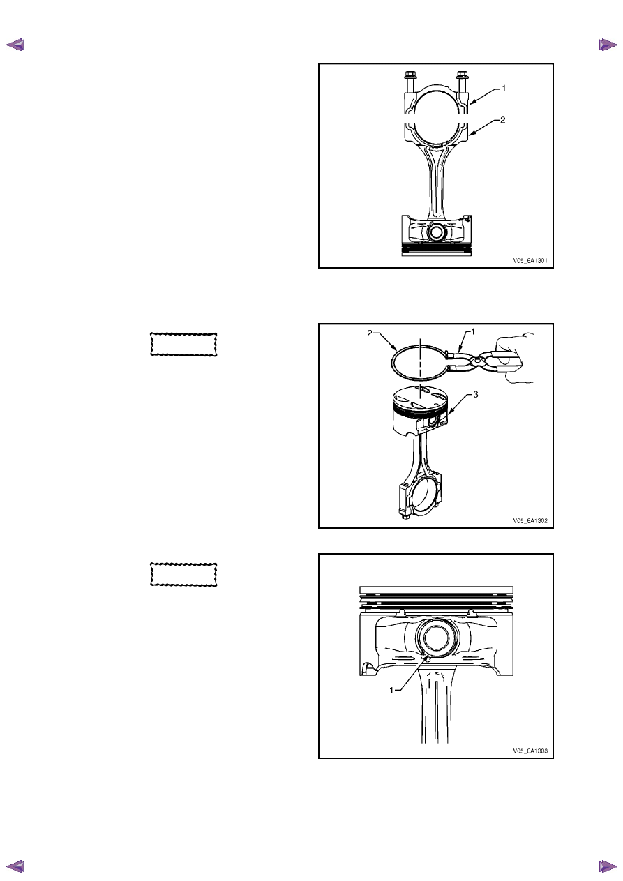
14
Remove the upper connecting rod bearing from the
connecting rod (2).
Figure 6A1 – 468
15
Remove the lower connecting rod bearing (1) from
the connecting rod cap (2).
Figure 6A1 – 469
Engine Mechanical – V6
Page 6A1–268
Page 6A1–268
N O T E
The cap and rod are a matched set and must be
kept together.
16
Reattach the connecting rod cap (1) to the connecting
rod (2) to prevent damage to their mating surfaces.
17
Repeat steps 4 to 16 for the remaining piston and
connecting rod assemblies.
Figure 6A1 – 470
Disassemble
CAUTION
A piston ring expander must be used to
remove and install the piston rings. Only
expand the rings far enough to fit over the
piston lands. If the rings are overexpanded,
the top ring will shatter and the others will
distort.
1
Remove the piston rings (2) using a piston ring
expander (1). Place each ring in a clean shop towel
for storage.
Figure 6A1 – 471
CAUTION
Do not reuse the piston pin retainers.
2
Remove the piston pin retainers by using the removal
access notch (1) in the side of the piston. Discard the
piston pin retainers.
Figure 6A1 – 472
Engine Mechanical – V6
Page 6A1–269
Page 6A1–269
3
Slide the piston pin (1) out of the piston (2). The
piston will disconnect from the connecting rod.
Figure 6A1 – 473
Clean and Inspect
Piston Cleaning Procedure
CAUTION
Do not use a wire brush to clean any part of
the piston.
1
Clean the piston skirts and the pins with a suitable solvent.
2
Clean the piston ring grooves with a groove cleaner. Ensure the oil ring holes and slots are clean.
Safety glasses must be worn when using
compressed air.
3
Dry the piston with compressed air.
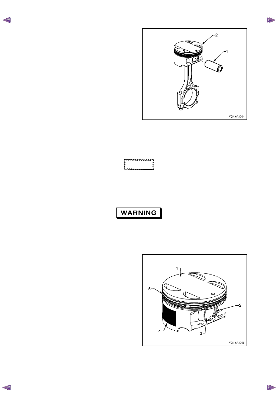
Piston Inspection Procedure
1
Inspect the pistons for the following conditions:
•
eroded areas at the top of the piston (1),
•
piston pin retainer grooves for burrs (2),
•
worn piston pin bores or worn piston pins (3),
•
scuffed or damaged skirt coating (4),
•
ring grooves for cracks, nicks or burrs that may
cause binding (5), and
•
warped or worn ring lands.
2
Replace pistons that show any signs of damage or
excessive wear.
Figure 6A1 – 474
Engine Mechanical – V6
Page 6A1–270
Page 6A1–270
Piston Measurement
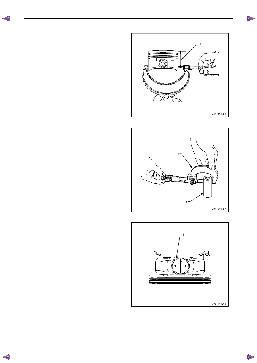
1
Measure piston width using the following procedure:
a
Using an outside micrometer, measure the
width of the piston at 30 mm below the crown
top (1), at the thrust surfaces of the piston,
perpendicular to the piston pin centreline.
b
Compare the measurement of the piston to its
original cylinder by subtracting the piston width
from the cylinder diameter.
c
Check your measurements with specifications,
refer to
5 Specifications
.
d
If the clearance obtained through measurement
is greater than the provided specifications and
the cylinder bores are within specification,
replace the piston.
Figure 6A1 – 475
2
Measure the piston pin bore to piston pin (2)
clearances using the following procedure:
a
Piston pin bores and pins must be free of
varnish or scuffing.
b
Use an outside micrometer (1) to measure the
piston pin in the piston contact areas.
Figure 6A1 – 476
3
Using an inside micrometer, measure the piston pin
bore (1). Compare the result with the piston pin
diameter and piston pin to piston pin bore clearance
listed in the specifications, refer to
5 Specifications
.
4
If the clearance is excessive, determine which piece
is out of specification and replace as required.
5
Replace the piston if any of its dimensions are out of
specification.
6
If the new piston does not meet clearance
specifications, the cylinder block may need to be
oversized to 0.25 mm. There is only one size of
oversized pistons and rings available for service.
Figure 6A1 – 477
Нет комментариевНе стесняйтесь поделиться с нами вашим ценным мнением.
Текст