Isuzu KB P190. Manual — part 805

Fuel System – V6
Page 6C – 18
4.4
Fuel Tank Assembly
Figure 6C – 17
Legend
1
Front Fuel Tank Strap Bolt
2
Front Fuel Tank Strap
3
Rear Side Shield
4 Fuel
Tank
5 Evaporative
Line
6
Fuel Filler Hose
7
Rear Under Shield Plastic Strap
8
Rear Fuel Tank Strap Bolt
9
Rear Fuel Tank Strap
10 Under
Shield
11
Front Under Shield Plastic Strap
12
Evaporative Line and Quick
Connector
13
Fuel Lines and Quick Connector
14
Main Fuel Supply Line
15 Fuel
Filter
16 Side
Shield
17 Retainer
Fuel System – V6
Page 6C – 19
Remove
• A depressurised fuel system contains fuel
in the fuel filter and fuel lines that can be
spilled during service operations.
• Fuel vapour remains in the fuel tank even
when completely empty. Seal all openings
in the fuel tank using suitable material or a
plastic plug. Ensure no naked flames or
other ignition sources are nearby. Ensure
all cellular phones (and transmission
devices that may cause any metal objects
to become unintentional receiving
antennas) are switched off.
• Place a dry chemical (Class
B) fire
extinguisher nearby before performing any
on-vehicle service procedures. Failure to
follow these precautions may result in
personal injury.
1
Remove the fuel pump relay, refer to 8A Electrical Body and Chassis.
2
Depressurise the fuel system, refer to 3.4
Fuel System Depressurisation.
Never drain or store fuel into an open
container, due to the possibility of fire or
explosion.
3
Siphon the fuel tank, using commercially-available equipment.
Before proceeding, clean all traces of dirt and
other foreign material from the top of the fuel
tank, near the modular fuel pump and sender
assembly.
7
Place a drain tray under the fuel filter area.
Fuel can spill from the disconnected filter.
Fuel System – V6
Page 6C – 20
8
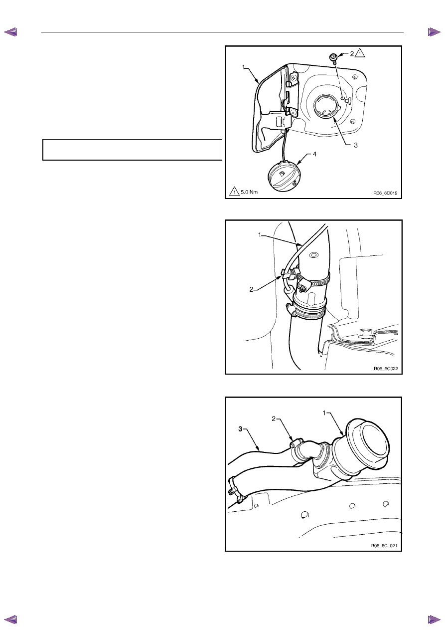
From behind the fuel filler door (1), unscrew the fuel
filler cap (4) and cover the end of the fuel filler neck
with a suitable material to prevent foreign objects from
entering the fuel tank.
9
Remove the screw (2) securing the fuel filler neck (3)
to the fuel filler pocket.
10
Remove the front half of the right-hand rear
wheelhouse liner, refer to 10 Cab.
Fuel filler neck attaching screw
torque specification . . . . . . . . . . . ..5.0 Nm
Figure 6C – 18
11
Unclip the fuel filler door release cable (1) from the
retainer on the fuel filler neck (2).
Figure 6C – 19
12
Lower the fuel filler neck and breather hose assembly.
13
Loosen the clamp (2) and disconnect the fuel tank
breather hose (3) from the fuel filler neck (1).
Figure 6C – 20

Fuel System – V6
Page 6C – 21
14
Remove the clamp (1) from the fuel filler neck and
disconnect from the rubber fuel tank inlet hose (2),
place the removed filler neck (3) in a safe location.
15
Raise the vehicle, preferably on a hoist, refer to
0A General Information.
Figure 6C – 21
Wear safety glasses when using compressed
air. Do not blow compressed air onto any
body part.
16
Use compressed air to ensure that all dirt and foreign
materials are removed from all fuel connections before
the parts are disconnected.
17
Disconnect the quick-connect fitting from the fuel
supply line at the front of the fuel tank (1) and the
evaporative line quick-connect fitting at the rear of the
fuel tank (2), refer to 4.1
Fuel Lines And Quick
Connect Fittings.
Figure 6C – 22
18
Remove the bolt securing the front fuel tank strap (1) to the crossmember and remove the strap (2), refer to Figure
6C – 17.
Support the fuel tank with stands or have an
assistant on hand to help in the fuel tank
removal.
19
Remove the bolt from the rear fuel tank strap (8) then remove the strap (9) refer to Figure 6C – 17.
20
Lower the rear of the fuel tank enough to allow access to the fuel pump electrical connector, release the connector
clip and remove the connector from the socket.
21
Lower the fuel tank from the vehicle, ensuring the fuel tank inlet and breather hoses do not foul on any obstruction
during the process.
22
Remove the fuel tank from the vehicle.
Нет комментариевНе стесняйтесь поделиться с нами вашим ценным мнением.
Текст