Isuzu KB P190. Manual — part 110
4A-24 PROPELLER SHAFT
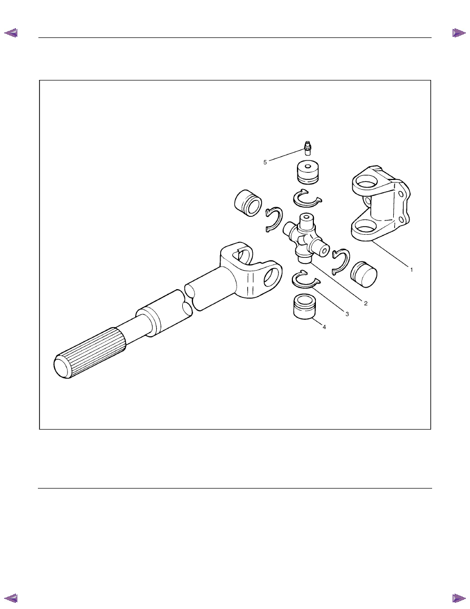
Universal Joint Disassembly and
Reassembly
401RW055
Legend
1.
Flange
Yoke
2.
Spider
3.
Snap
Ring
4. Needle Roller Bearing
5.
Grease
Fitting
PROPELLER SHAFT 4A-25
401RS028
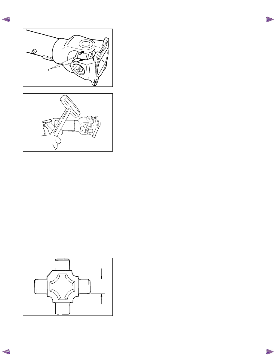
Disassembly
1. Apply alignment marks (1) on the yokes of the universal
joint, then remove snap ring.
401RS006
2. Tap out the needle roller bearing by gently striking the
shoulder of the yoke, using a mallet or a copper hammer.
3. Make sure of proper position for reinstallation by applying
setting marks, then remove spider.
Inspection and Repair
Make necessary correction or parts replacement if wear,
damage, corrosion or any other abnormal condition is found
through inspection.
NOTE:
When any part of the journal assembly (spider, needle roller
bearing) requires replacement, be sure to replace the entire
assembly.
Check the following parts for wear, damage, noise or any other
abnormal conditions:
1. Spider
2. Needle roller bearing
3. Yoke
4. Flange
5. Constant velocity joint
401RS007
Outside Diameter of Spider Pin
Standard: 17.00 mm (0.6693 in)
Limit: 16.99 mm (0.6689 in)
4A-26 PROPELLER SHAFT
401RS027
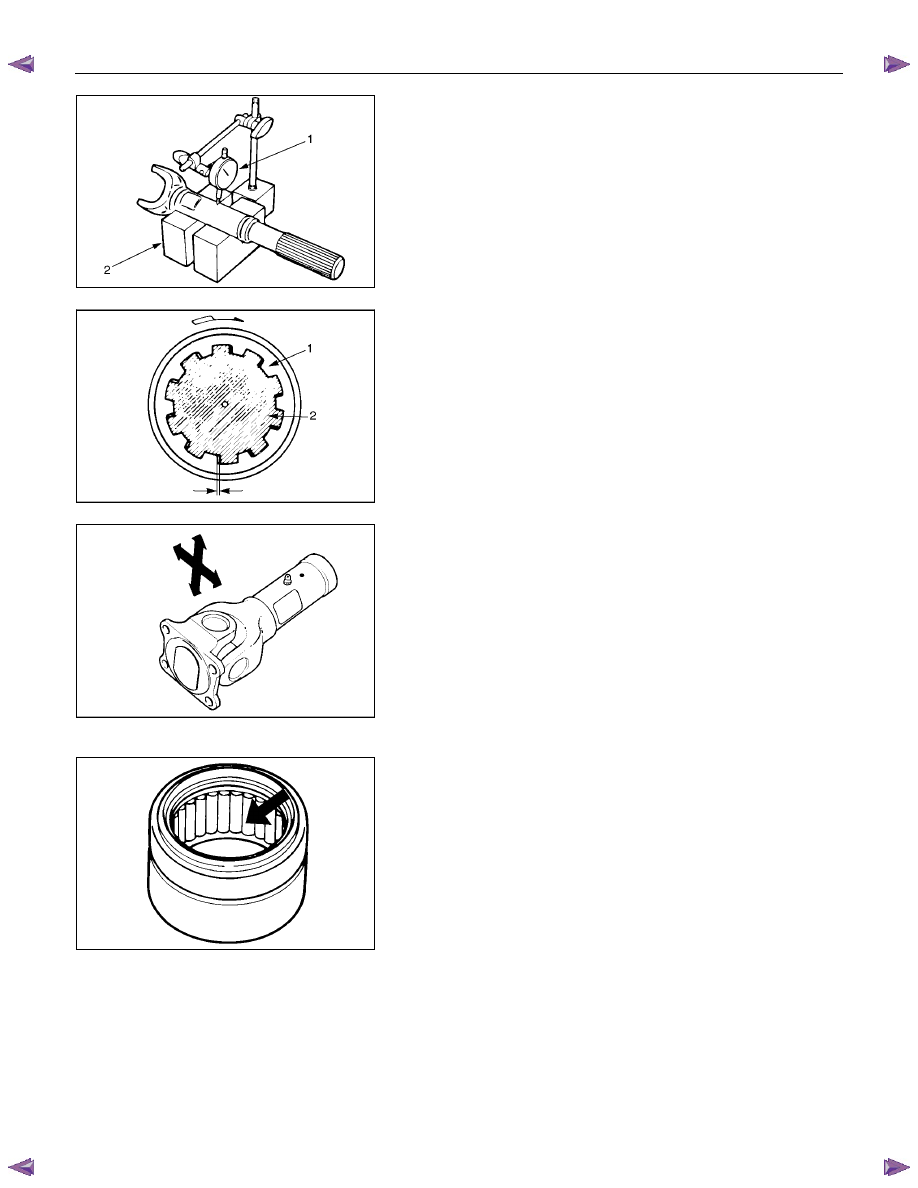
Propeller Shaft Run-out
Support the ends of the propeller shaft on V-blocks (2) and
check for run-out by holding the probe of a dial indicator (1) in
contact with the center part of the shaft. If the amount of run-
out is beyond the standard value for assembly, correct with a
bench press or replace the shaft with a new propeller shaft
assembly.
Standard: 0.3 mm (0.012 in)
Limit: 0.5 mm (0.02 in)
401RS009
Play in Splines in Normal Direction of Rotation
Check the amount of play between the sleeve yoke (1) and the
propeller shaft spline (2) in the direction of rotation, using a
pointed feeler gauge.
Standard: 0.073-0.156 mm (0.003-0.006 in)
Limit: 0.3 mm (0.012 in)
401RS010
Play in Universal Joint
Limit: Less than 0.1 mm (0.004 in)
401RS011
Reassembly
1. Install spider to flange yoke. Be sure to install the spider by
aligning the setting marks made during disassembly.
2. Apply a molybdenum-disulfide grease or multi-purpose type
grease NLGI No. 2 to inside of the bearing cap.
Grease Amount: Approx. 1.2 g (0.042 oz)
PROPELLER SHAFT 4A-27
401RS012
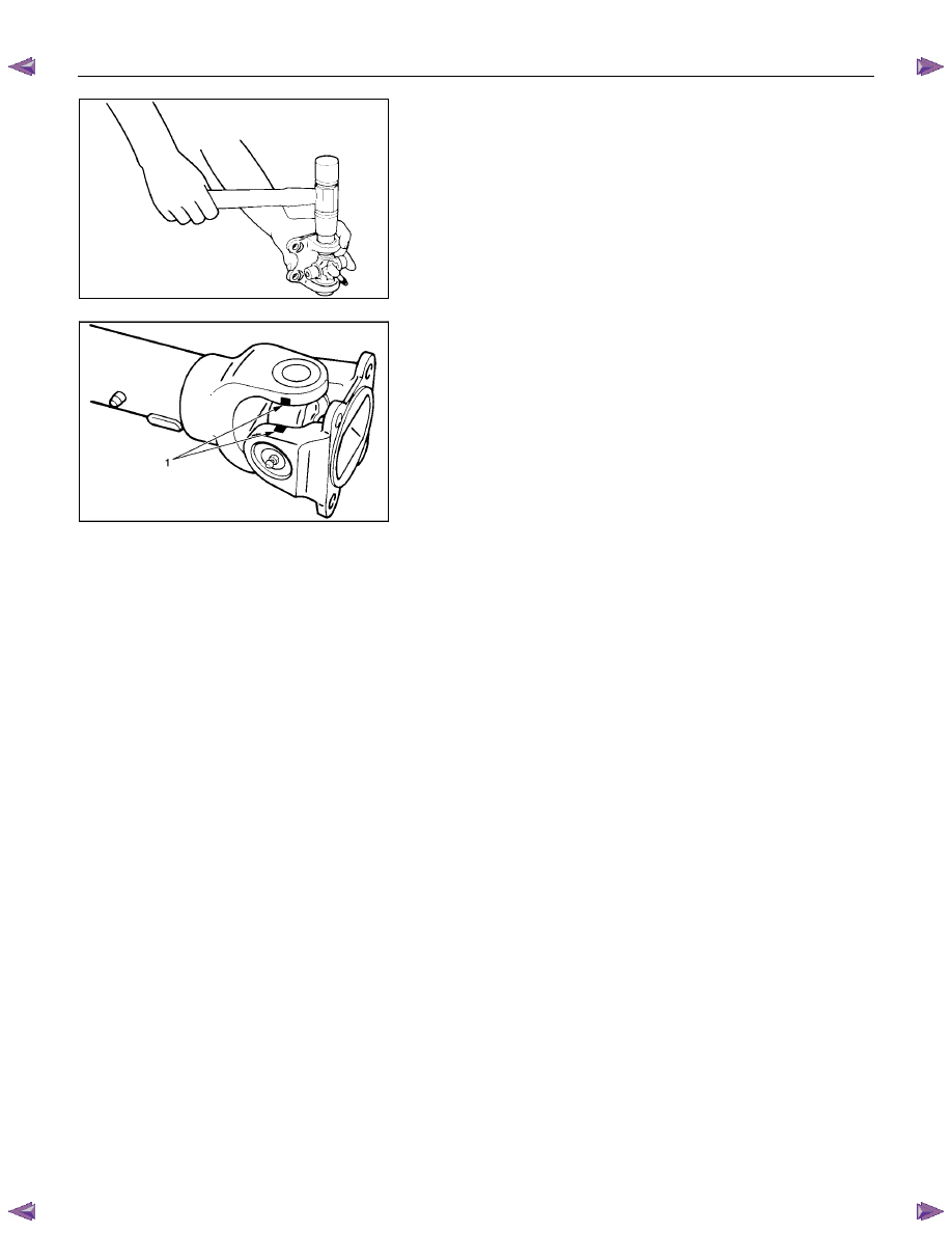
3. Using either a mallet (or copper hammer) or a press, install
the needle roller bearing into the yoke so that the snap ring
can be installed in its groove.
CAUTION:
The needle roller bearing cannot be installed smoothly if it
is set at an incorrect angle with the flange and excessive
hammering will damage the needle roller bearing.
401RS028
4. Align setting marks (1) and join the yokes.
5. Install snap ring.
NOTE:
Discard used snap rings and install new ones.
When the bearing cap is in position, select and attach a snap
ring of suitable thickness so that the end play of the spider pin
is held within 0.1 mm (0.004 in).
Snap ring thickness and Identification color
1.50 mm (0.059 in); Light Blue
1.53 mm (0.060 in); White
1.56 mm (0.061 in); Pink
1.59 mm (0.063 in); Yellow
1.62 mm (0.064 in); Green
1.65 mm (0.065 in); Brown
1.68 mm (0.066 in); Not colored
NOTE:
Be sure to use snap rings of the same thickness
on both sides.
Нет комментариевНе стесняйтесь поделиться с нами вашим ценным мнением.
Текст