Isuzu KB P190. Manual — part 331
6E-290 Engine Control System (4JH1)
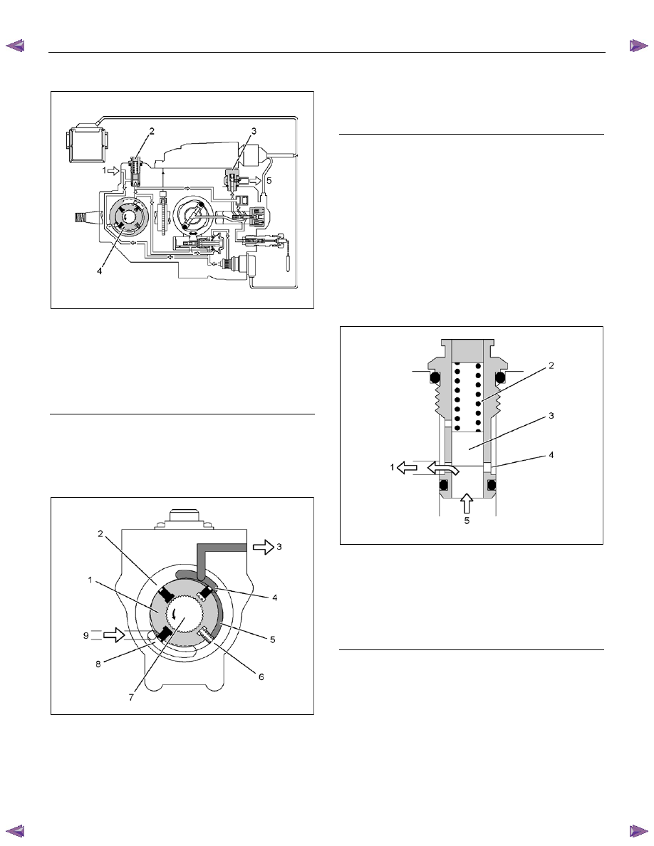
Low Pressure Fuel Circuit Description
RTW66ESH002101
Legend
1. Fuel
Suction
2. Regulating
Valve
3. Overflow
Valve
4. Feed
Pump
5. To Fuel Tank
The low pressure fuel circuit must supply sufficient fuel
to the high pressure fuel circuit. The main components
are the feed pump, the regulating valve and the
overflow valve.
Feed Pump
RTW66ESH002201
Legend
1. Rotor
2. Casing
Ring
3. Fuel
Supply
4. Outlet
5. Chamber
6. Vane
7. Driveshaft
8. Inlet
9. Fuel
Suction
The feed pump is driven by the drive shaft, performs
suction and supply of fuel. The vanes assembled in the
rotor are pressed against the inside of the casing ring
by spring forces and centrifugal force during rotation to
form chambers. When the vanes rotate, the volume of
these chambers increase when they reach recesses the
casing ring connected to the inlet port. Pressure then
decreases and fuel is drawn in. When the chambers
have passed the inlets and recesses, the volume
decreases and the fuel is compressed. Fuel pressure
increases until the chamber reaches the outlet, where
the fuel passes through the regulating valve to the high
pressure fuel circuit.
Regulating Valve
RTW66ESH002301
Legend
1. To
Inlet
2. Spring
3. Valve
Piston
4. Port
5. From
Outlet
When feed pump speed increases so that the delivery
pressure of the fuel delivered from the outlet exceeds
the regulating valve spring force, the plunger is pushed
upwards. Excess fuel passes through the ports and
returns to the inlet side, and the delivery pressure is
maintained within a specified range. When feed pump
speed decreases so that the delivery pressure
decreases, the plunger is pushed downwards by spring
force to close the port.

Engine Control System (4JH1) 6E-291
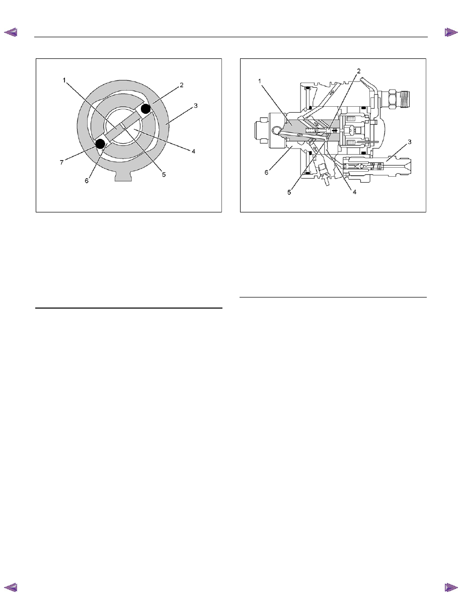
Overflow Valve
RTW66ESH002401
Legend
1. Valve
Holder
2. Port
3. To Fuel Tank
4. Orifice
Port
5. From Fuel Tank
6. Ball
Valve
7. Spring
When the pressure of the fuel, returned from the
distributor head, exceeds the spring force, the overflow
valve's ball valve is pushed up. Excess fuel presses
through the port and returns to the tank, and fuel
pressure inside the pump chamber does not exceed a
specified pressure. The flow of excess fuel serves
cooling and automatic bleeding of the fuel pump during
operation. Also the orifice port is installed to assist in
automatic air bleeding.
High Pressure Fuel Circuit Description
RTW66ESH002501
Legend
1. Fuel Injection Pump Control Unit (PCU)
2. Distributor
Head
3. Fuel Injection Solenoid Valve
4. Constant Pressure Valve (CPV)
5. Radial
Plunger
In addition high pressure generating device, the high
pressure circuit also consists of fuel piping, and devices
to set the beginning of injection and fuel injection
quantity. The main components are as follows:
• High pressure generation: Radial Plunger
• Fuel distribution: Distributor Head
• Beginning of injection timing: Timing Device
• Prevention of secondary injection: Constant
Pressure Valve (CPV)
6E-292 Engine Control System (4JH1)
Radial Plunger
RTW66ESH002601
Legend
1. Radial
Plunger
2. Internal
Cam
3. Cam
Ring
4. Rotor
Shaft
5. Plunger
Chamber
6. Roller
Shoe
7. Roller
While the radial plungers assembled to the rotor shaft
rotate, they are held against the inside of the cam ring
(via the roller shoes and rollers) by fuel delivery
pressure from the feed pump and centrifugal force. The
radial plungers perform rotational movement as well as
internal cam induced reciprocating movement to suck in
and compress the fuel in the plunger chamber.
Distributor Head
RTW66ESH002701
Legend
1. Rotor
Shaft
2. Valve
Needle
3. Constant Pressure Valve (CPV) Holder
4. High Pressure Outlet
5. Distributor
Shaft
6. Barrel
The distributor head distribute the high pressure fuel
that has flowed through the rotating rotor shaft's
distributor slits and the barrel's high pressure outlets (4
cylinders: 4) to the engine cylinders via the constant
pressure valve (CPV) and the nozzle holder
assemblies. The fuel injection solenoid valve needle
changes the passage to the radial plunger high
pressure pump between fuel suction and fuel
compression.
Engine Control System (4JH1) 6E-293
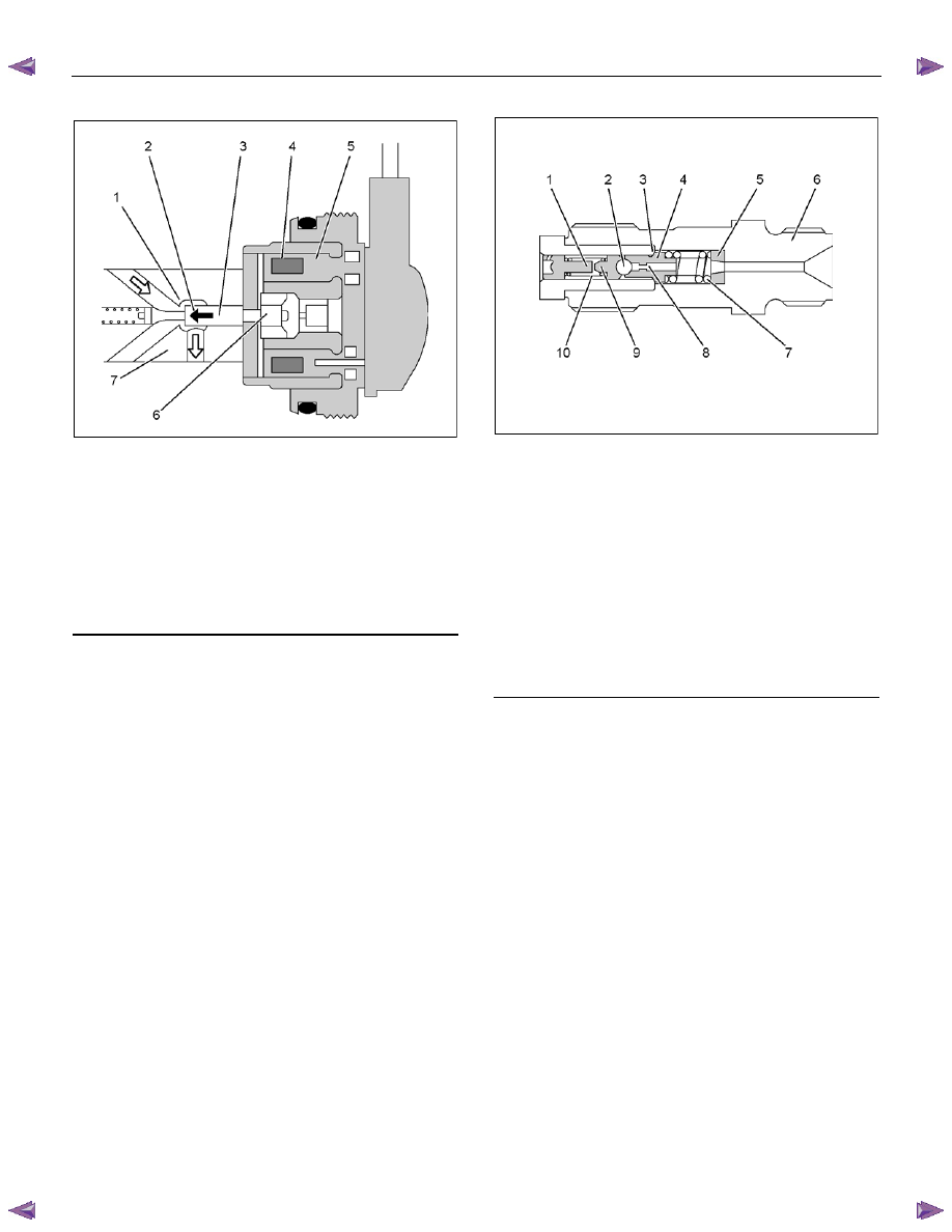
Fuel Injection Solenoid Valve
RTW66ESH002801
Legend
1. Valve
Seat
2. Valve Closing Direction
3. Valve
Needle
4. Coil
5. Magnet
6. Magnet
Anchor
7. Rotor
Shaft
The fuel injection solenoid valve consists of a valve
seat, a valve needle, and a magnet anchor (a movable
iron core), a coil and a magnet. The valve needle
rotates together with the rotor shaft. When current
controlled by the fuel injection pump control unit (PCU)
flows to the coil, the magnet anchor and the valve
needle are pushed towards the valve seat. When the
valve seat is completely closed by the valve needle, the
fuel in the high pressure passage is isolated from the
low pressure passage, is compressed by the radial
plunger high pressure pump, and injected into the
engine cylinder through the nozzle holder assembly.
When the required injection quantity is reached, the
current to the coil is cut, the valve seat opens and
injection of fuel is completed.
Constant Pressure Valve (CPV)
RTW66ESH002901
Legend
1. Plug
2. Ball
3. Seat
4. Valve
5. Spacer
6. Holder
7. Valve
Spring
8. Oriffice
9. Ball
Support
10. Spring
The constant pressure valve (CPV) consists of a holder,
a spacer, a valve spring, a valve, a seat, a ball, a ball
support, a spring and a plug. The valve is equipped with
an orifice to suppress the reflected pressure wave (the
cause of secondary injection) caused by nozzle closing
at the end of the injection and maintains a stable
pressure in the injection pipe (residual pressure) to
ensure stabilized injection timing for subsequent
injection. The valve is opened by pressurized fuel and
this high pressure fuel is delivered to the nozzle holder
assembly.
Нет комментариевНе стесняйтесь поделиться с нами вашим ценным мнением.
Текст