Isuzu KB P190. Manual — part 1113
7A2-168 TRANSMISSION CONTROL SYSTEM (JR405E)
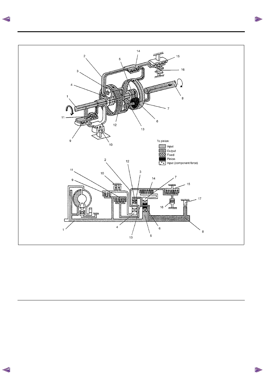
Third Gear
Legend
1. Input shaft
2. Front planetary carrier
3. Front pinion gear
4. Front sun gear
5. Rear sun gear
6. Rear pinion gear
7. Rear internal gear
8. Output shaft
9. Reverse clutch
10. 2-4 brake
11. High clutch
12. Front internal gear
13. Rear planetary carrier
14. Low clutch
15. Low & reverse brake
16. Low one-way clutch
17. Parking pawl
The driving force from the input shaft (1) is transmitted
to the rear sun gear (5) and reverse & high clutch drum.
As in the case of the 1st gear and 2nd gear, the low
clutch (14) is engaged and the movement of the rear
internal gear (7) is restricted. Since the high clutch (11)
is engaged, the driving force from the input shaft (1) is
directly transmitted to the rear internal gear (7). As a
result, the speed of the rear sun gear (5) and the rear
internal gear (7) becomes the same as that of the input
shaft (1), so that the rear pinion gear rotates (6) not
independently but together with the rear sun gear (5)
and rear internal gear (7). When decelerating, the
engine brake is applied.
TRANSMISSION CONTROL SYSTEM (JR405E) 7A2-169
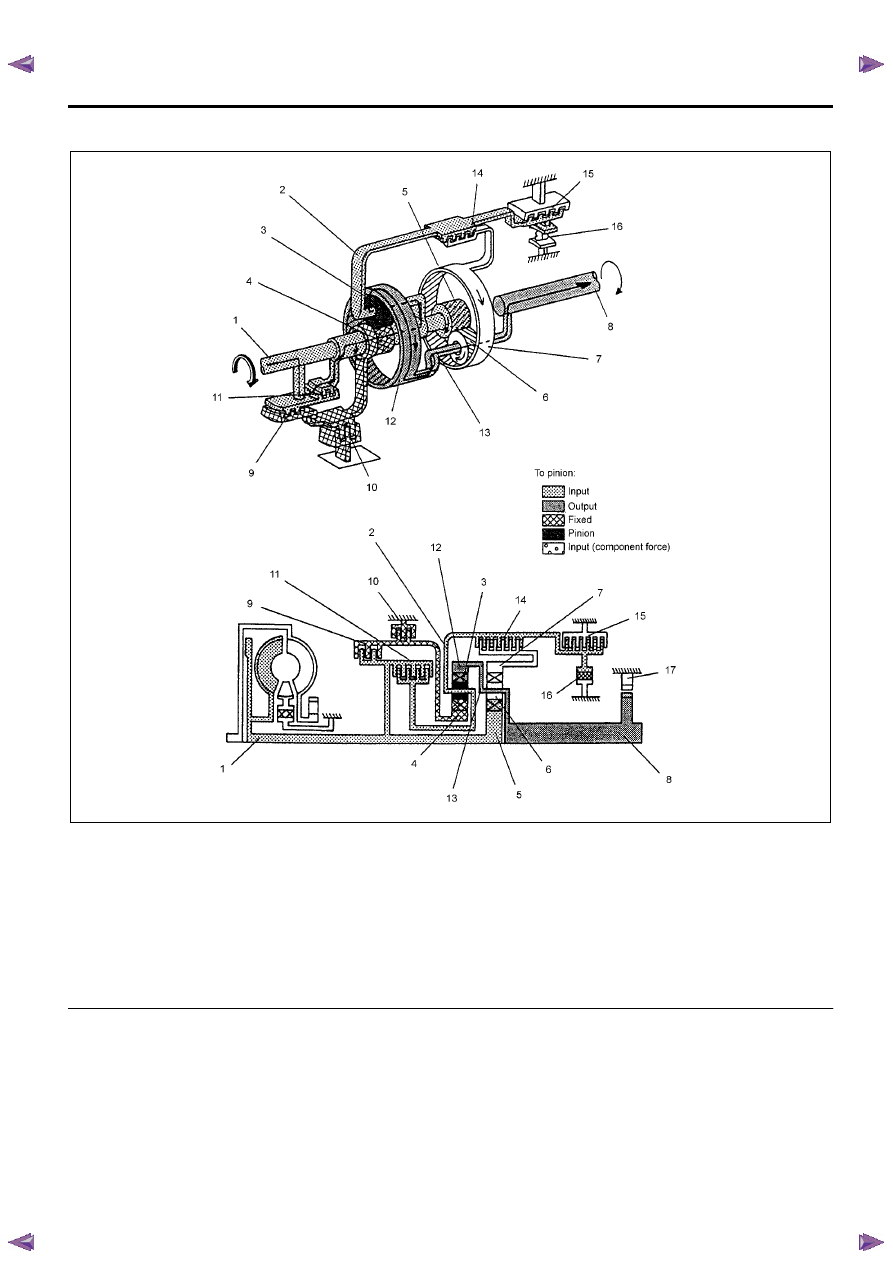
Fourth Gear
Legend
1. Input shaft
2. Front planetary carrier
3. Front pinion gear
4. Front sun gear
5. Rear sun gear
6. Rear pinion gear
7. Rear internal gear
8. Output shaft
9. Reverse clutch
10. 2-4 brake
11. High clutch
12. Front internal gear
13. Rear planetary carrier
14. Low clutch
15. Low & reverse brake
16. Low one-way clutch
17. Parking pawl
The driving force from the input shaft (1) is transmitted
to the rear sun gear (5) and reverse & high clutch drum.
Since the 2-4 brake (10) is engaged, the front sun gear
(4) is fixed. In addition to this the high clutch (11) is
engaged. As a result, the front pinion gear (6) rotates
itself together with other gears clockwise. This rotation
increases the speed of rotation of the front internal gear
(12) and is transmitted to the output shaft (8).
7A2-170 TRANSMISSION CONTROL SYSTEM (JR405E)
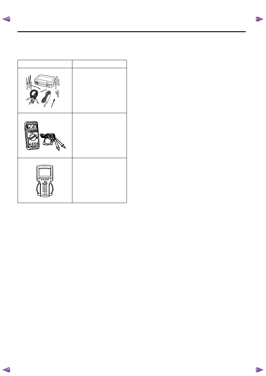
Special Tools and Equipment
Special Tools and Equipment
Illustration
Tool Number / Description
5-8840-2835-0 (J-35616-C)
Connector Test Adapter Kit
(With Test Lamp)
5-8840-0285-0 (J-39200)
Digital Multimeter
Tech 2 Kit
5884028350
ON-VEHICLE SERVICE (JR405E) 7A3-1
SECTION 7A3
ON-VEHICLE SERVICE (JR405E)
TABLE OF CONTENTS
PAGE
Description . . . . . . . . . . . . . . . . . . . . . . . . . . . . . .. 7A3 – 2
Automatic Transmission Fluid (ATF) . . . . . . . . . . . . . . . . . . . 7A3 – 2
ATF Level . . . . . . . . . . . . . . . . . . . . . . . . . . . . . . . 7A3 – 2
ATF Change . . . . . . . . . . . . . . . . . . . . . . . . . . . . . . 7A3 – 3
Transmission Control Module (TCM) . . . . . . . . . . . . . . . . . . . 7A3 – 5
Inhibitor Switch . . . . . . . . . . . . . . . . . . . . . . . . . . . ... 7A3 – 6
Speed Sensor . . . . . . . . . . . . . . . . . . . . . . . . . . . . .. 7A3 – 8
Turbine Sensor . . . . . . . . . . . . . . . . . . . . . . . . . . . ... 7A3 – 9
Power and 3rd Start Switch . . . . . . . . . . . . . . . . . . . . . . ... 7A3 – 9
Select Lever . . . . . . . . . . . . . . . . . . . . . . . . . . . . . . 7A3 –10
Shift Cable . . . . . . . . . . . . . . . . . . . . . . . . . . . . . ... 7A3 –13
Solenoids, Oil Pressure Switch and Oil Temperature Sensor . . . . . . . . . 7A3 –16
Control Valve Assembly . . . . . . . . . . . . . . . . . . . . . . . . . 7A3 –18
Flushing the Transmission Fluid Cooler and Line . . . . . . . . . . . . . .. 7A3 –19
Transmission Assembly . . . . . . . . . . . . . . . . . . . . . . . . . 7A3 –20
Special Service Tool . . . . . . . . . . . . . . . . . . . . . . . . . ... 7A3 –23
Нет комментариевНе стесняйтесь поделиться с нами вашим ценным мнением.
Текст