Isuzu KB P190. Manual — part 76
POWER-ASSISTED STEERING SYSTEM 3B-43
6. Install the driver knee bolster assembly.
7. Install the steering lower cover and engine hood
opening lever.
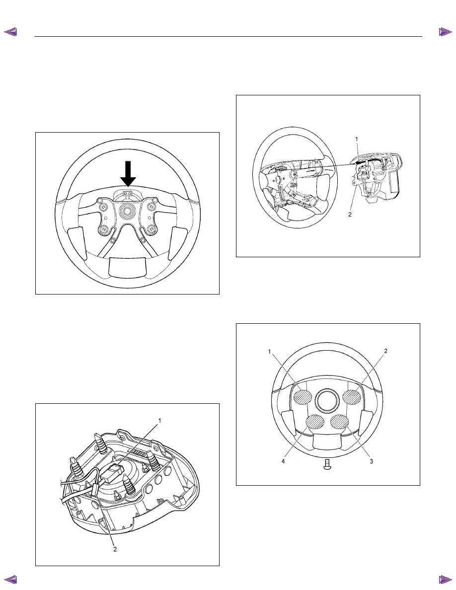
8. Install the steering wheel and align the setting
marks.
Refer to the adjustment method in case a mark has
not been applied in this section.
NOTE: Confirm SRS and horn harness connector is
fixed by the steering wheel.
RTW73BSH000701
CAUTION: Never apply force to the steering wheel in
the direction of the shaft by using a hammer or
other impact tools in an attempt to remove the
steering wheel. The steering shaft is designed as an
energy absorbing unit.
9. Tighten the steering wheel fixing nut to the specified
torque.
Torque: 35 N
⋅⋅⋅⋅m (3.6 kgf⋅⋅⋅⋅m/26 lb⋅⋅⋅⋅ft)
10. Support the inflator module and carefully connect
the SRS connector (1) and horn lead (2) (with SRS
air bag).
RTW73BSH001101
11. Connect the horn leads at center of wheel (without
SRS air bag).
NOTE: The horn leads (1) are passed along the top of
the bracket (2).
(Plastic type steering wheel only)
RTW73BSH000801
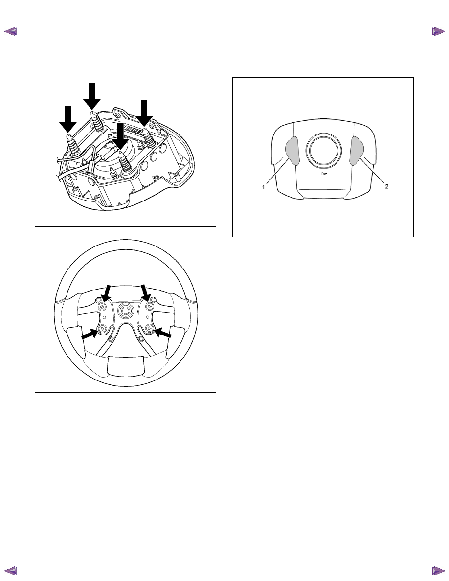
12. Push the horn pad at areas 1-4.
Tighten the horn pad fixing screw to the specifed
torque (without SRS air bag)
Torque: 3 N
⋅⋅⋅⋅m (0.3 kgf⋅⋅⋅⋅m/26 lb⋅⋅⋅⋅in)
NOTE: A horn pad should not be struck during
attachment.
RTW73BSH000201
3B-44 POWER-ASSISTED STEERING SYSTEM
13. Align each snap stud of driver air bag to the holes on
steering wheel. (with SRS air bag)
RTW73BSH001201
RTW73BSH000401
14. Push the SRS air bag at area-1 (1) and area-2 (2). At
that time confirm the audible noise of each stud.
(with SRS air bag)
RTW73BSH000301
15. Enable the SRS (Refer to "Enabling the SRS" in this
section). (with SRS air bag)
16. Install driver knee bolster (reinforcement).
17. Install instrument panel lower cover then install the
engine hood opening lever.
18. Connect the SRS connector (with SRS air bag).
19. Connect the battery "-" terminal cable. (with SRS air
bag)
20.
Turn the ignition switch to "ON" while watching
warning light and check - the light should flash 7
times and then go off. If lamp does not operate
correctly, refer to Restraints section.
POWER-ASSISTED STEERING SYSTEM 3B-45
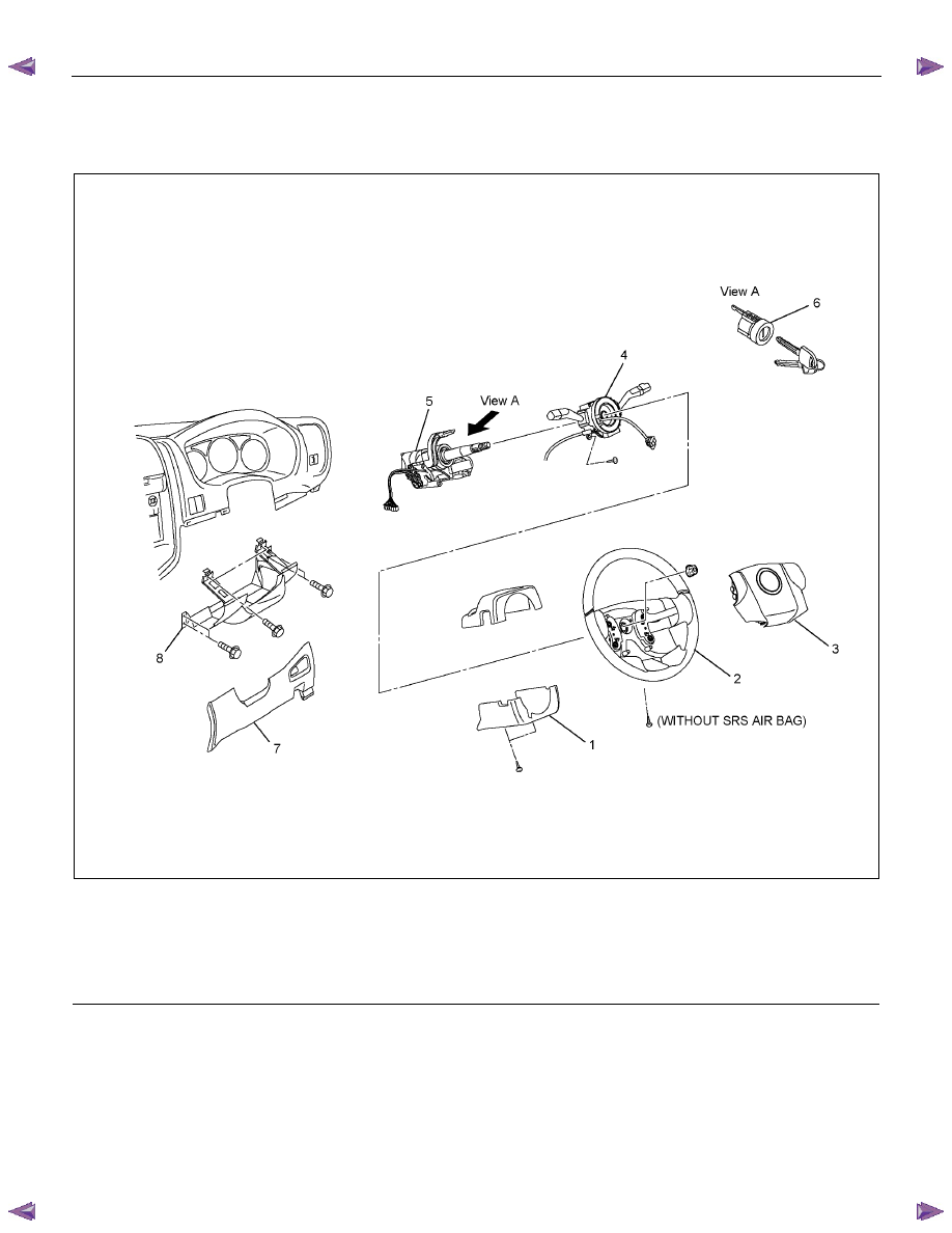
Lock Cylinder
Lock Cylinder and Associated Parts
RTW73BLF000401
Legend
(1) Steering Column Cover
(2) Steering Wheel
(3) Inflator Module or Horn pad
(4) Combination Switch and SRS Coil Assembly
(5) Steering Column Assembly
(6) Lock Cylinder Assembly
(7) Instrument Panel Lower Cover
(8) Driver Knee Bolster (reinforcement)
Removal
1. Turn the steering wheel so that the vehicle's wheels
are pointing straight ahead.
2. Turn the ignition switch to "LOCK".
3. Disconnect the battery "-" terminal cable, and wait at
least 5 minutes (with SRS air bag).
4. Disconnect the yellow 2-way SRS connector located
under the steering column (with SRS air bag).
3B-46 POWER-ASSISTED STEERING SYSTEM
CAUTION: The wheels of the vehicle must be
straight ahead and the steering column in the
"LOCK" position before disconnecting the steering
wheel. Failure to do so will cause the coil assembly
to lose its centering which will cause damage to the
coil assembly (with SRS air bag).
5. Remove the engine hood opening lever and
steering lower cover.
6. Remove driver knee bolster (reinforcement).
7. Disable the SRS (Refer to "Disabling the SRS" in
this section) (with SRS air bag).
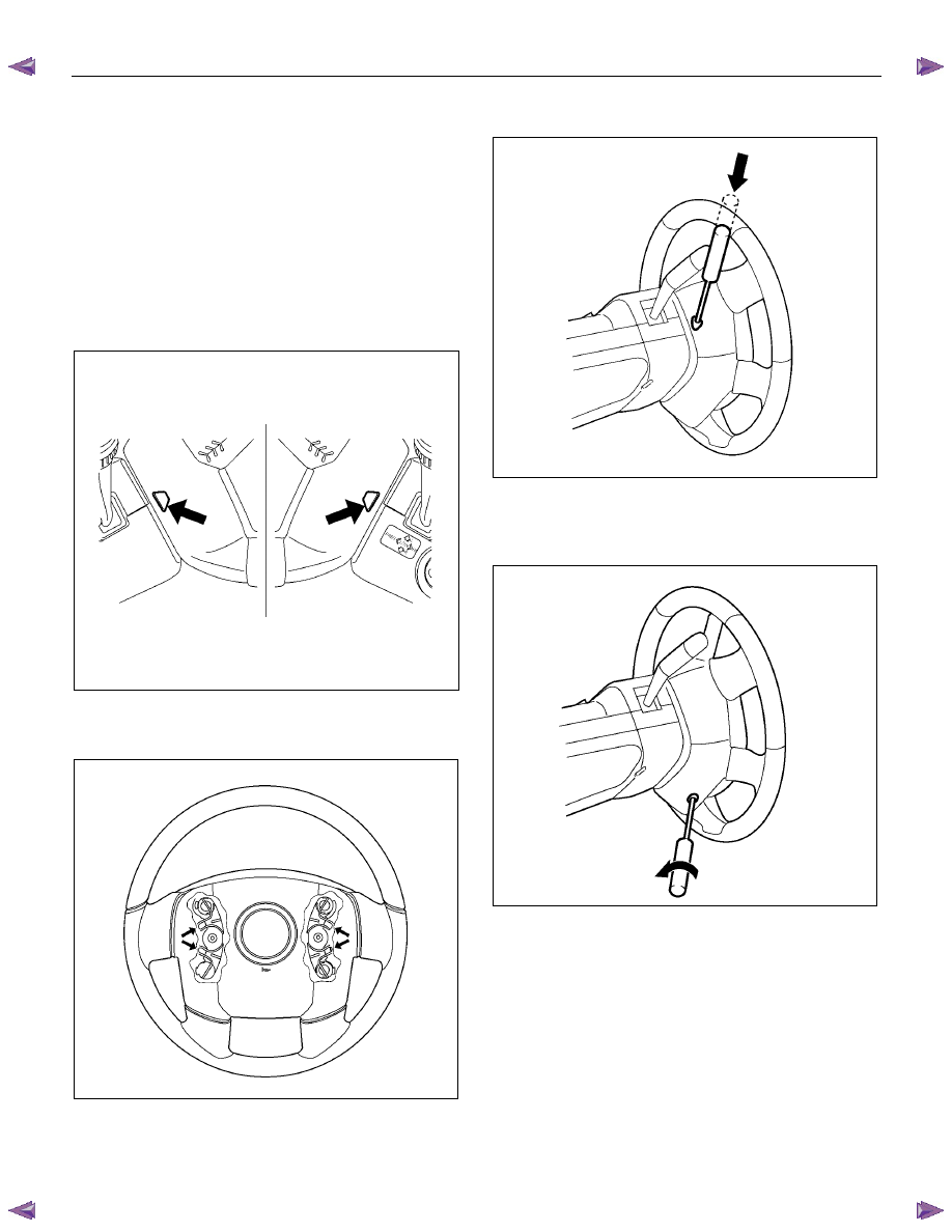
8. Check the holes on both sides of the steering cover
(with SRS air bag).
060R300025
9. Check the position of the pins in thier holes. Push
the pin in the direction of the arrow (with SRS air
bag).
RTW73BSH000101
10. Push the four pins with a φ 5~6 mm (0.20~0.24 in)
bar (with SRS air bag).
060R300031
11. Cancel the lock to release the four pins (with SRS
air bag).
12. Loosen the horn pad fixing screw at the rear of the
steering wheel (without SRS air bag).
430R300009
Нет комментариевНе стесняйтесь поделиться с нами вашим ценным мнением.
Текст