Isuzu KB P190. Manual — part 1216
7D-34 TRANSFER CASE
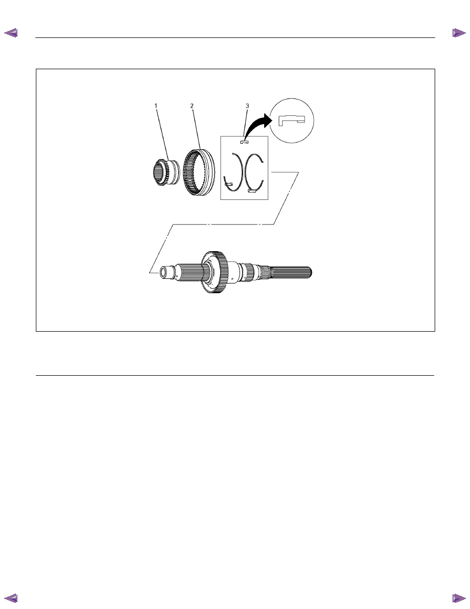
14. Insert the H-L sleeve into the main shaft.
226R300023
Legend
(1) H-L Sleeve
(3) Synchronizer Key and Key Spring
(2) 2-4 Sleeve
15. Install the sleeve to the H-L shift assembly.
16. Install the sleeve to the 2-4 shift assembly.
17. Coat the area around each of the shift assembly
insertion holes (transfer case) with transfer oil.
18. Install the main shaft together with the H-L shift
assembly and the 2-4 shift assembly to the shift drum.
TRANSFER CASE 7D-35
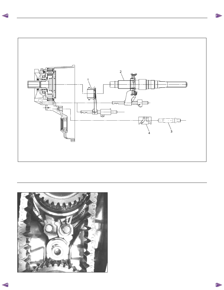
19. Align the shift shaft splines with the shift drum and
install the shafts to the drum.
RTW320MF000201
Legend
(1) H-L Sleeve and Shift ASM
(3) Shift Shaft
(2) 2-4 Sleeve ASM with Main Shaft and Shift ASM
(4) Shift Drum
NOTE: Be careful in the direction of an assembly.
P1010041/020124
20. Coat the main shaft with oil.
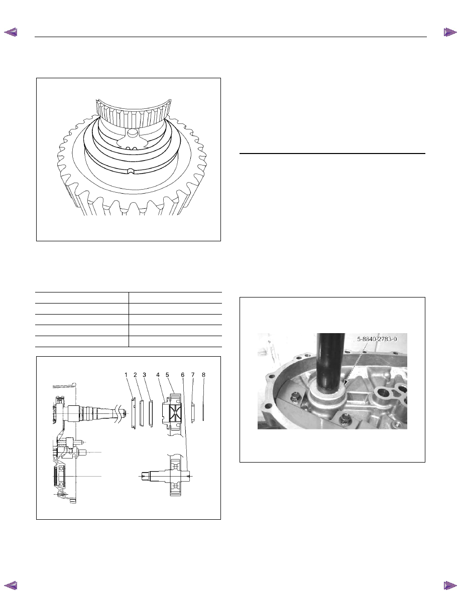
21. Align the block ring, the outside ring, and the inside
ring with the 2-4 hub assembly and install them.
22. Assemble the sprocket, transfer chain, and front
output shaft.
23. Install the sprocket, transfer chain, and front output
shaft to the main shaft and the transfer case.
7D-36 TRANSFER CASE
24. Align the sprocket thrust washer with the main shaft
groove and install it.
226R300009
25. Select a snap ring that will allow minimum axial play.
Insert it to the main shaft installation groove.
mm (in)
Snap ring thickness
Identification color
2.15 (0.085)
Red
2.10 (0.083)
Not colored
2.05 (0.081)
Blue
2.00 (0.079)
White
226R300008
Legend
(1) Block Ring
(2) Outside Ring
(3) Inside Ring
(4) Sprocket
(5) Transfer Chain
(6) Front Output Shaft
(7) Thrust Washer
(8) Snap Ring
26. Measure the snap ring external diameter. If the
measured diameter is outside the specified range, a
larger or smaller snap ring must be used.
Snap ring outside diameter (Standard):
53.0
±±±± 0.5 mm (2.09 ±±±± 0.02 in)
27. Position the rear cover so that its mating surfaces are
facing up.
28. Use a press and an installer (5-8840-2783-0) to install
the front output shaft needle bearing. The installer
must be aligned with the bearing manufacturer's
name (stamped into the bearing).
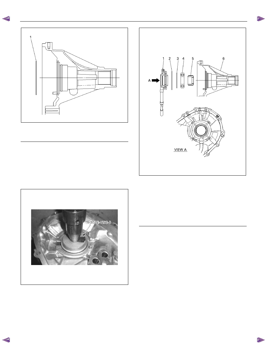
29. Install the oil pump wire snap ring to the rear cover.
TRANSFER CASE 7D-37
226R300005
30. Temporarily install the speedometer drive gear to the
inside of the rear cover. Pay close attention to
installation direction.
31. Use a press and an installer (9-8522-1268-0) to install
the rear output shaft ball bearings. Do not drive the
ball bearings into place with a hammer.
32. Install the rear output shaft retaining ring.
33. Place the oil pump in its specified position.
34. Secure the oil pump strainer to the rear cover and
tighten the bolts to the specified torque.
Oil pump and rear cover bolt torque:
15 N·m (1.5 kgf·m/11 lb·ft)
226R300010
35. Apply Loctite FMD 127 to the mating surfaces of the
rear cover and the transfer case. Be sure that the
Loctite is evenly applied to the inside surfaces of the
bolt holes with no gaps.
Legend
(1) Oil Pump Assembly
(2) Wire Snap Ring
(3) Retaining Ring
(4) Ball Bearing
(5) Speedometer Gear Drive Gear
(6) Rear Cover
Legend
(1) Wire Snap Ring
Нет комментариевНе стесняйтесь поделиться с нами вашим ценным мнением.
Текст