Isuzu KB P190. Manual — part 731
Engine Mechanical – V6
Page 6A1–147
Page 6A1–147
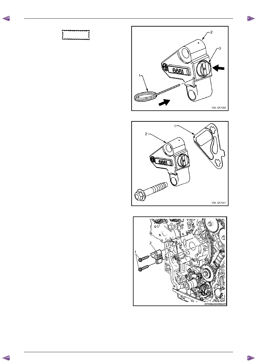
CAUTION
If Tool No. EN 46112 (1) is not removed from
the tensioner body (2), the tensioner
shaft (3) will remain in the locked position
and no tension will be placed on the timing
chain, this will cause damage to the engine.
25
Compress the tensioner shaft into the body and lock
the left-hand secondary timing chain tensioner by
inserting Tool No. EN 46112 into the access hole in
the side of the tensioner body.
26
Slowly release pressure on the left-hand secondary
timing chain tensioner. The tensioner should remain
compressed.
Figure 6A1 – 192
27
Install a new left-hand secondary timing chain
tensioner gasket (1) to the tensioner (2).
28
Install the left-hand secondary timing chain tensioner
bolts through tensioner and gasket.
29
Ensure the left-hand secondary timing chain tensioner
mounting surface on the left-hand cylinder head does
not have any burrs or defects that would affect the
sealing of the new gasket.
Figure 6A1 – 193
30
Place the left-hand secondary timing chain tensioner
(2) into position and loosely install the bolts (1) to the
cylinder head.
Figure 6A1 – 194
Engine Mechanical – V6
Page 6A1–148
Page 6A1–148
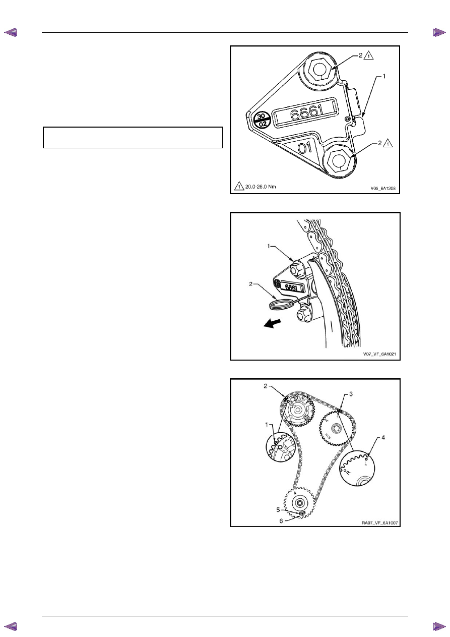
31
Verify the proper placement of the left-hand
secondary timing chain tensioner gasket tab (1).
32
Tighten the left-hand secondary timing chain
tensioner bolts (2) to the correct torque specification.
Secondary timing chain tensioner
attaching bolt torque specification. . ...20.0 – 26.0 Nm
Figure 6A1 – 195
33
Release the left-hand secondary timing chain
tensioner (1) by pulling out Tools No. EN 46112 (2)
and unlocking the tensioner shaft.
Figure 6A1 – 196
34
Verify the left-hand secondary timing chain timing
mark alignments (1 to 6).
Figure 6A1 – 197
Engine Mechanical – V6
Page 6A1–149
Page 6A1–149
Primary Timing Chain Components – Excluding MY06 Update
1
If previously removed, install the left-hand secondary
timing chain components, refer to Left-hand
Secondary Timing Chain Components in this Section.
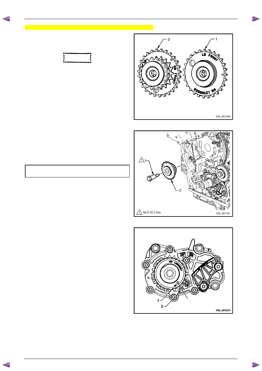
CAUTION
The right-hand camshaft intermediate
sprocket (2) is marked with the letters RB
and ‘FRONT’, and the left-hand sprocket (1)
is marked with the letters LB and 'FRONT'
Ensure the correct sprocket is used and the
FRONT text is facing forwards when
installed.
2
Ensure the right-hand camshaft intermediate
sprocket (2) is selected and orientated correctly.
Figure 6A1 – 198
3
Install the right-hand camshaft intermediate sprocket
(2).
4
Install the sprocket bolt (1) and tighten to the correct
torque specification.
Camshaft intermediate sprocket
attaching bolt torque specification. . ...58.0 – 72.0 Nm
Figure 6A1 – 199
5
Ensure that the crankshaft sprocket timing mark (1) is
aligned with the indexing mark (2) on the oil pump
housing.
Figure 6A1 – 200
Engine Mechanical – V6
Page 6A1–150
Page 6A1–150
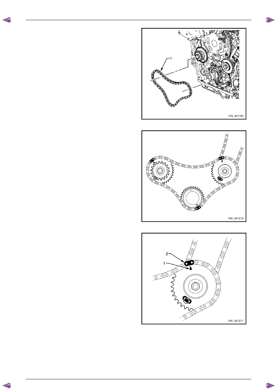
6
Install the primary timing chain (1).
Figure 6A1 – 201
7
Wrap the primary timing chain around the large
sprockets of each camshaft intermediate sprocket
and the crankshaft sprocket aligning the bright plated
chain links as follows:
Figure 6A1 – 202
8
The left-hand camshaft intermediate sprocket timing
mark (1) will align with a bright plated primary timing
chain link (2).
Figure 6A1 – 203
Нет комментариевНе стесняйтесь поделиться с нами вашим ценным мнением.
Текст