Isuzu KB P190. Manual — part 732
Engine Mechanical – V6
Page 6A1–151
Page 6A1–151
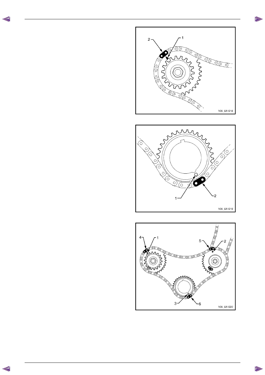
9
The right-hand camshaft intermediate sprocket timing
mark (1) will align with a bright plated primary timing
chain link (2).
Figure 6A1 – 204
10
The crankshaft sprocket timing mark (1) will align with
a bright plated timing chain link (2).
Figure 6A1 – 205
11
Ensure all the timing marks (1, 2 and 3) are properly
aligned with the bright plated timing chain links (4, 5
and 6).
Figure 6A1 – 206
Engine Mechanical – V6
Page 6A1–152
Page 6A1–152
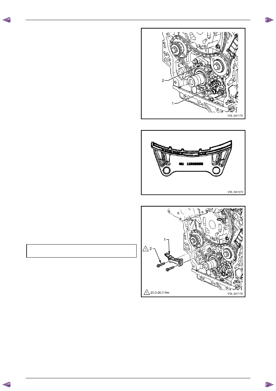
N O T E
Do not remove the primary timing chain lower
guide (1). The primary timing chain lower guide
is not serviced separately. If the primary timing
chain lower guide must be replaced, the oil
pump assembly (2) must be replaced.
Figure 6A1 – 207
12
Ensure the primary timing chain upper guide is
selected and orientated correctly.
Figure 6A1 – 208
13
Install the primary timing chain upper guide (1).
14
Install the primary timing chain upper guide bolts (2)
and tighten to the correct torque specification.
Primary timing chain upper guide
attaching bolt torque specification. . ...20.0 – 26.0 Nm
Figure 6A1 – 209
Engine Mechanical – V6
Page 6A1–153
Page 6A1–153
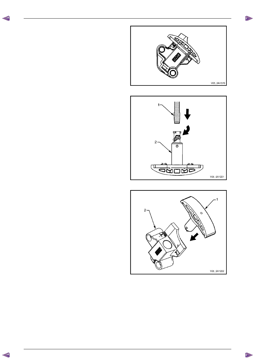
15
Ensure that the primary timing chain tensioner is
being installed.
Figure 6A1 – 210
16
Reset the primary timing chain tensioner.
N O T E
To reset the tensioner, use a suitably sized flat
blade screwdriver (1) or Tool No. J 45027 (4) to
wind the plunger in a clockwise direction, into
the tensioner shaft (2).
Figure 6A1 – 211
17
Install the tensioner shoe assembly (1) into the
primary timing chain tensioner body (2).
Figure 6A1 – 212
Engine Mechanical – V6
Page 6A1–154
Page 6A1–154
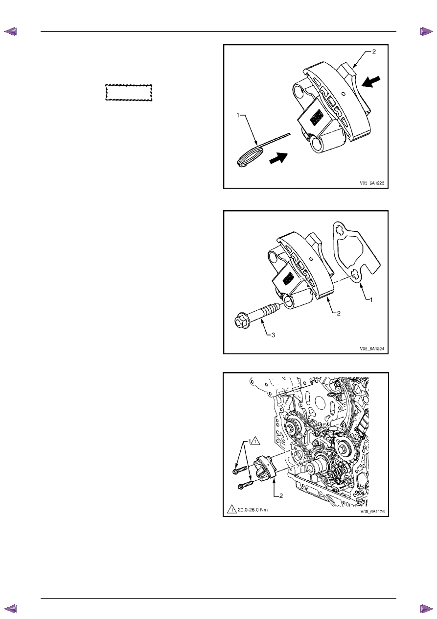
18
Compress the shoe assembly into the body (2) and
lock the primary timing chain tensioner by inserting
Tool No. EN 46112 into the access hole in the side of
the body.
CAUTION
If Tool No. EN 46112 (1) is not inserted into
the tensioner body, the plunger will remain
in the locked position and no tension will be
placed on the timing chain.
19
Slowly release pressure on the primary timing chain
tensioner. The primary timing chain tensioner should
remain compressed.
Figure 6A1 – 213
20
Install a new primary timing chain tensioner gasket (1)
to the tensioner (2).
21
Install the primary timing chain tensioner bolts (3)
through tensioner and gasket.
22
Ensure the primary timing chain tensioner mounting
surface on the engine block does not have any burrs
or defects that would affect the sealing of the new
gasket.
Figure 6A1 – 214
23
Place the primary timing chain tensioner (2) into
position and loosely install the bolts (1) to the engine
block.
Figure 6A1 – 215
Нет комментариевНе стесняйтесь поделиться с нами вашим ценным мнением.
Текст