Isuzu KB P190. Manual — part 752
Engine Mechanical – V6
Page 6A1–231
Page 6A1–231
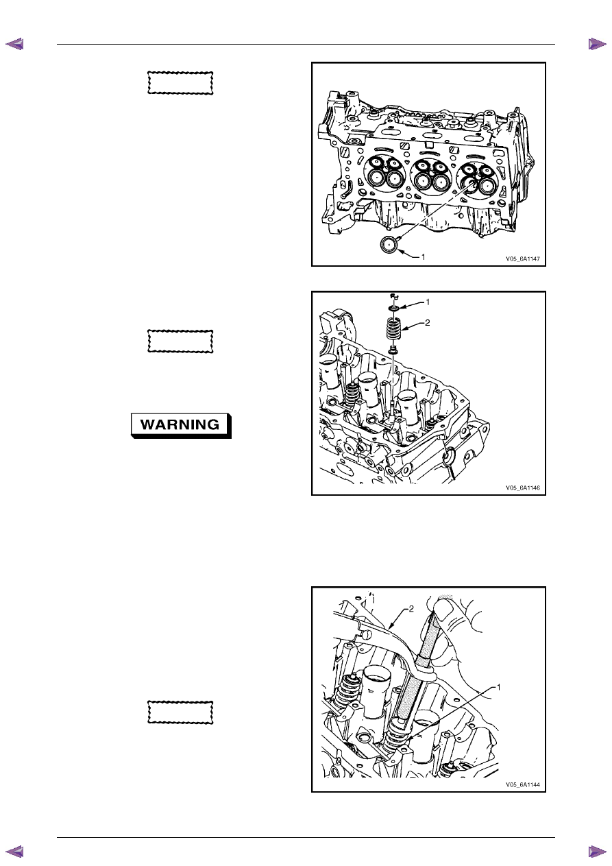
CAUTION
The valve stem oil seal must not come loose
from the valve guide when the valve (1) is
installed.
6
Insert the valve into the valve guide until it bottoms on
the valve seat.
Figure 6A1 – 391
7
Position the valve spring (2) on the spring seat (1).
8
Place the valve spring retainer onto the valve spring.
CAUTION
Do not compress the valve springs less than
24.0 mm. Contact between the valve spring
retainer and the valve stem oil seal can
cause potential valve stem oil seal damage.
Compressed valve springs (1) have high
tension against the valve spring
compressor (2). Valve springs that are not
correctly compressed by, or are released
from, the valve spring compressor can be
ejected from the valve spring compressor
with intense force. Use care when
compressing or releasing the valve spring
with the valve spring compressor and when
removing or installing the valve stem keys.
Failing to use care may cause personal
injury.
Figure 6A1 – 392
9
Compress the valve spring using valve spring
compressor Tool No. J-8062 and adaptor Tool No.
EN-46119.
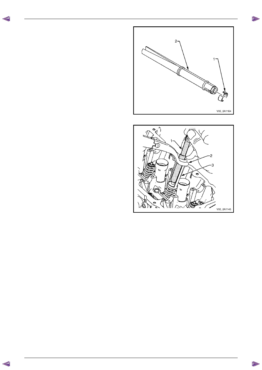
CAUTION
Ensure correct directional placement of
valve collets (1) in Tool No. EN-46117 (2).
The valve collets must be installed with the
tapered end towards the valve stem seal.
Figure 6A1 – 393
Engine Mechanical – V6
Page 6A1–232
Page 6A1–232
10
With the spring compressed, install the valve collets
into Tool No. EN 46117.
Figure 6A1 – 394
11
Place the collets into position by pushing the tool (1)
downward and releasing tension on the valve spring
compressor (2).
12
Verify the valve collets are installed by placing a rag
over the valve tip and tapping with a dead-blow
hammer. The valve collets and the spring should
remain in place.
Figure 6A1 – 395
Engine Mechanical – V6
Page 6A1–233
Page 6A1–233
Reinstall
Right-hand Side (Bank 1) Cylinder Head
The reinstallation procedure for the right-hand side cylinder head assembly is the reverse of the removal procedure,
noting the following:
1
Ensure all fasteners are tightened to the correct torque specification.
2
Using crankshaft rotation Tool No. EN-46111 (1),
align the crankshaft sprocket timing mark (2) with the
indexing mark (3) on the oil pump housing.
Figure 6A1 – 396
3
Ensure the deck face is clean and the cylinder head
locating pins are securely mounted in the cylinder
block deck face.
4
Install a new right-hand cylinder head gasket (1)
using the deck face locating pins for retention.
Figure 6A1 – 397
5
Align the cylinder head with the locating pins.
6
Place the cylinder head in position on the deck face.
N O T E
Do not allow oil on the cylinder head bolt
bosses.
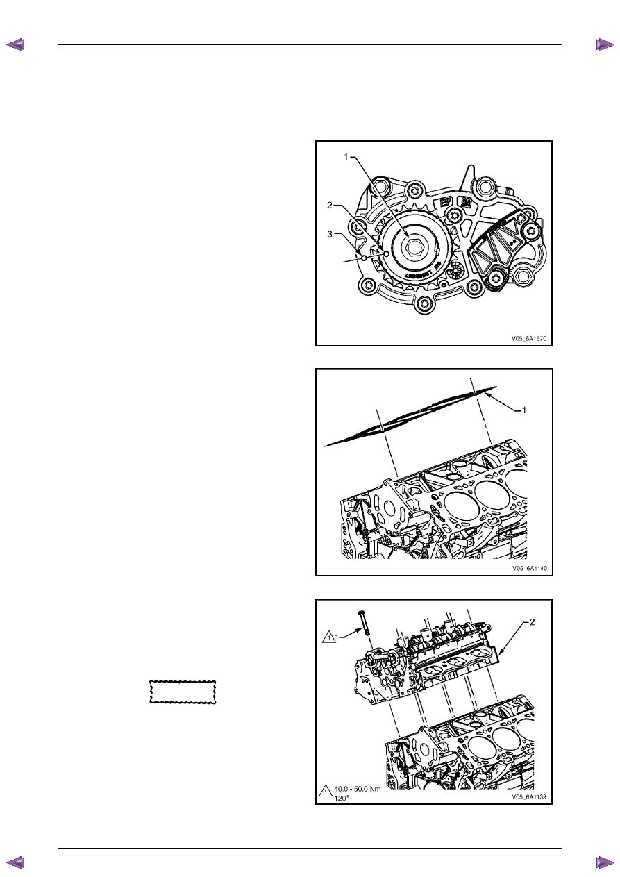
CAUTION
Do not reuse the old M11 cylinder head bolts
(1 to 8 inclusive).
7
Install new M11 cylinder head bolts (1) eight places
and tighten in the sequence shown and to the correct
torque specification.
Figure 6A1 – 398

Engine Mechanical – V6
Page 6A1–234
Page 6A1–234
Cylinder head M11 attaching bolt
torque specification:
Stage
1: . . . .40.0 – 50.0 Nm
Stage
2: . . . . . . . ..120°
Figure 6A1 – 399
Left-hand Side (Bank 2) Cylinder Head
The reinstallation procedure for the left-hand side cylinder head assembly is the reverse of the removal procedure, noting
the following:
1
Ensure all fasteners are tightened to the correct torque specification.
2
Using crankshaft rotation Tool No. EN-46111 (1),
align the crankshaft sprocket timing mark (2) with the
indexing mark (3) on the oil pump housing.
Figure 6A1 – 400
3
Ensure the deck face is clean and the cylinder head
locating pins are securely mounted in the cylinder
block deck face.
4
Install a new cylinder head gasket (1) using the deck
face locating pins for retention.
Figure 6A1 – 401
Нет комментариевНе стесняйтесь поделиться с нами вашим ценным мнением.
Текст