Isuzu KB P190. Manual — part 753
Engine Mechanical – V6
Page 6A1–235
Page 6A1–235
5
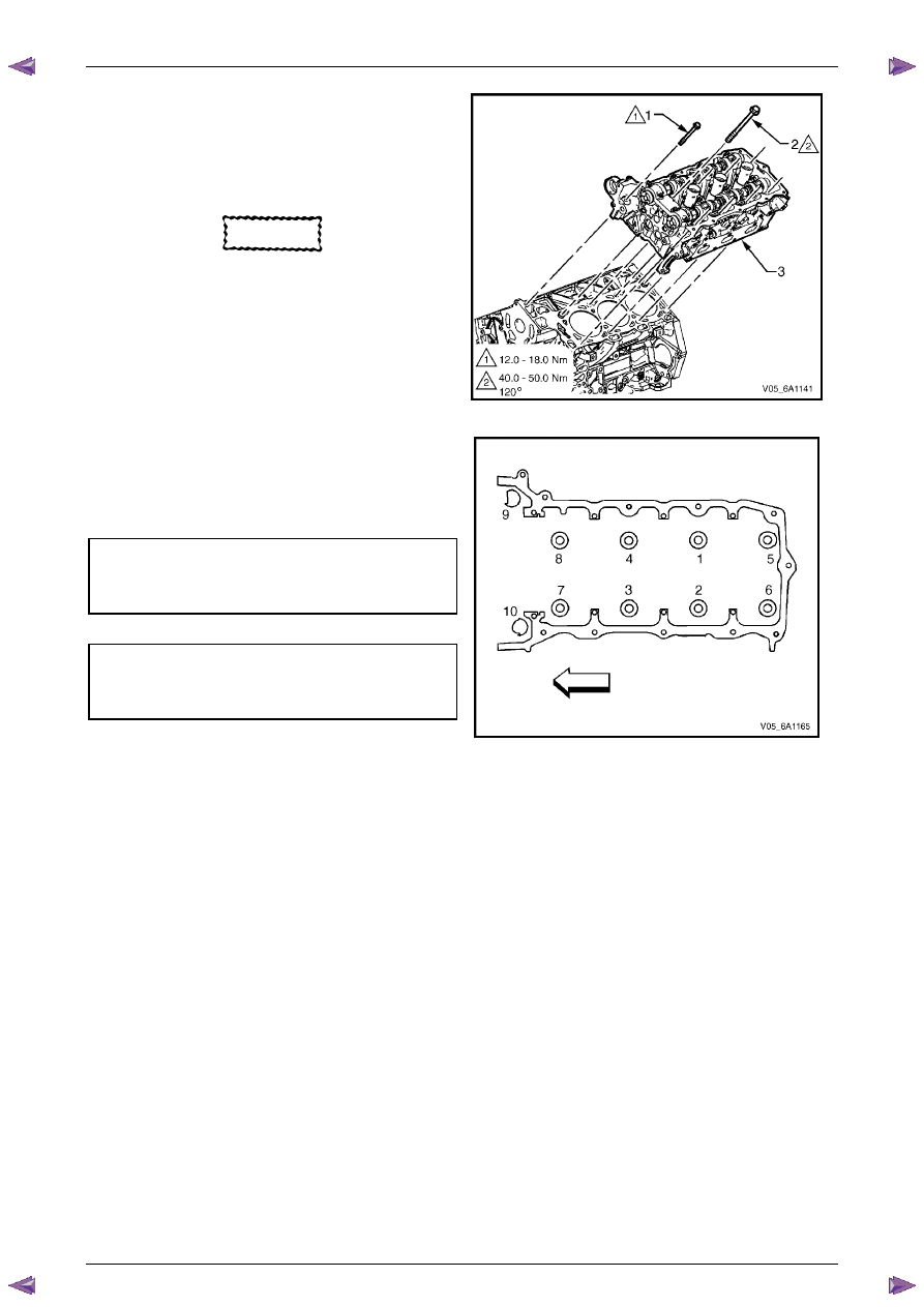
Align the cylinder head with the locating pins.
6
Place the cylinder head in position on the deck face.
N O T E
Do not allow oil on the cylinder head bolt
bosses.
CAUTION
Do not reuse the old M11 cylinder head bolts
(1 to 8 inclusive).
7
Install new M11 cylinder head bolt (1), eight places,
and tighten in the sequence shown and to the correct
torque specification.
Figure 6A1 – 402
8
Install the front M8 cylinder head bolt (2), two places,
and tighten in the sequence (9 and 10) and to the
correct torque.
Cylinder head M11 attaching bolt
torque specification:
Stage
1: . . . .40.0 – 50.0 Nm
Stage
2: . . . . . . . ..120°
M8 cylinder head bolt
torque specification
Stage
1: . . . .12.0 – 18.0 Nm
Stage
2: . . . . . . . . 60°
Figure 6A1 – 403
Engine Mechanical – V6
Page 6A1–236
Page 6A1–236
3.24 Engine Mounts and Brackets
Remove
1
Remove the exhaust manifold assembly from the side of the engine where the engine mount is to be removed,
refer to
3.11 Exhaust Manifold Assembly
.
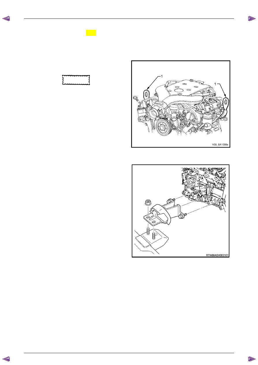
2
Fit the engine lift brackets, Tool No. EN-46114 (1) to
the cylinder heads.
CAUTION
Only lift the engine far enough to take the
weight off the engine mount, or damage to
the mount and lifting equipment failure may
occur.
3
Using an engine lifting crane, raise the side of the
engine where the mount is to be removed enough to
remove the weight from the engine mounts, and
create a slight tension in the lifting equipment.
Figure 6A1 – 404
4
Remove the left-hand or right-hand side engine
mount and bracket as required.
Figure 6A1 – 405
Engine Mechanical – V6
Page 6A1–237
Page 6A1–237
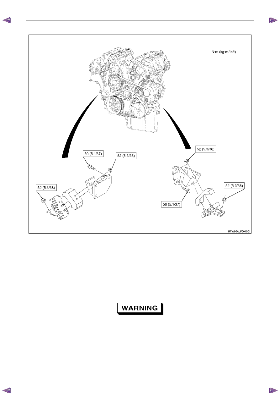
Engine Mount Location
Figure 6A1 – 406
Inspect
N O T E
Although the following procedure provides
information regarding on-vehicle engine mount
inspections, it is preferable to inspect the engine
mounts once removed from the vehicle.
1
Fit the engine lift brackets, Tool No. EN-4611 to the cylinder heads.
Only lift the engine enough to take the weight
off the engine mounts, or damage to the
mounts and lifting equipment failure may
occur.
2
Using a commercially available engine lifting crane, have an assistant raise the engine far enough to remove the
weight on the engine mounts and create a slight tension in the rubber.
3
Observe the engine mount while raising the engine.

Engine Mechanical – V6
Page 6A1–238
Page 6A1–238
4
Replace the engine mount if any of the following conditions are found:
•
The hard rubber surface is covered with heat check cracks,
•
The rubber is split through the centre of the engine mount, or
•
The rubber is separated from the metal plate portion of the engine mount.
5
Remove the engine lift brackets, Tool No. EN-46114 from the engine.
Reinstall
The reinstallation procedure for the engine mounts is the reverse of the removal procedure, noting the following:
Ensure all fasteners are tightened to the correct torque specification.
Engine mount bracket to
cylinder block attaching bolt
torque specification
. . . . . . . . . . . . . . . . 43.0 – 57.0 Nm
Engine mount to bracket attaching nut
torque specification
. . . . . . . . . . . . . . . . 70.0 – 90.0 Nm
Engine mount to frame attaching nut
torque specification
. . . . . . . . . . . . . . . . 44.0 – 60.0 Nm
Нет комментариевНе стесняйтесь поделиться с нами вашим ценным мнением.
Текст