Isuzu KB P190. Manual — part 93
FRONT SUSPENSION 3C-51
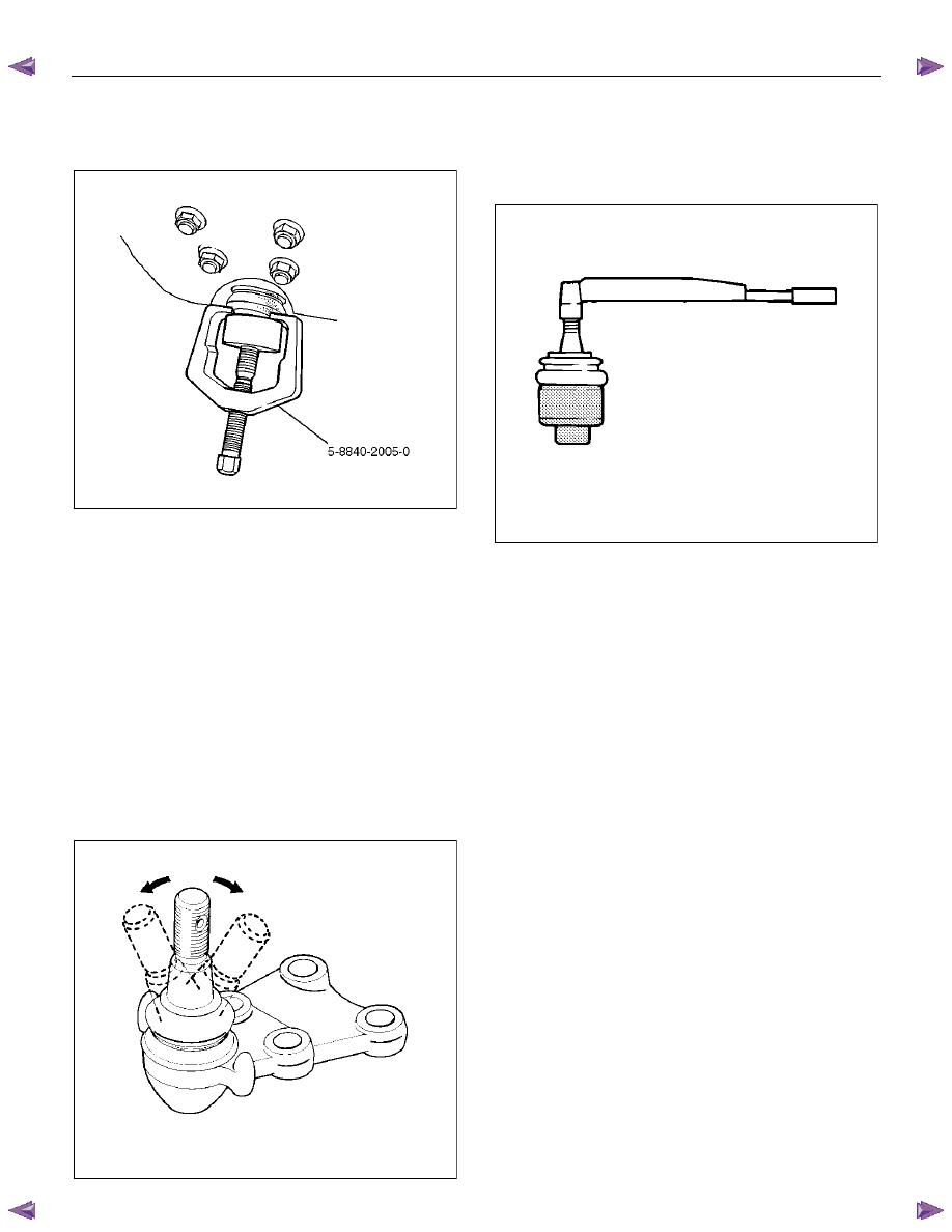
CAUTION: Be careful not to damage the ball joint
boot.
901RW271
7. Remove lower ball joint nut.
8. Remove lower ball joint bolt.
9. Remove lower ball joint.
Inspection and Repair
Make necessary parts replacement if wear, damage,
corrosion or any other abnormal condition is found
through inspection.
• Inspect the lower end boot for damage or grease
leak. Move the ball joint as shown in the figure to
confirm its normal movement.
• Inspect screw/taper area of ball for damage.
• If any defects are found by the above inspections,
replace the ball joint assembly with a new one.
450RS026
• After moving the ball joint 4 or 5 times, attach nut
then measure the preload.
Starting torque: 2.5-6.4 N
⋅⋅⋅⋅m (0.25-0.65 kgf⋅⋅⋅⋅m/1.8-
4.7 lb
⋅⋅⋅⋅ft)
450RS024
• If the above limits specified are exceeded, replace
the ball joint assembly.
Installation
1. Install lower ball joint.
2. Install lower ball joint bolt.
3. Install lower ball joint nut and tighten it to the
specified torque.
Torque: 127 N
⋅⋅⋅⋅m (13.0 kgf⋅⋅⋅⋅m/94 lb⋅⋅⋅⋅ft)
4. Install ball joint nut, then tighten it to the specified
torque with just enough additional torque to align
cotter pin holes. Install new cotter pin.
Torque: 147 N
⋅⋅⋅⋅m (15.0 kgf⋅⋅⋅⋅m/108 lb⋅⋅⋅⋅ft)

3C-52 FRONT SUSPENSION
Bump Rubber
Bump Rubber and Associated Parts
RTW63CMF000101
Legend
(1) Bolt
(2) Bump Rubber
Removal
1. Raise the vehicle and support the frame with
suitable safety stands.
2. Remove bolt.
3. Remove bump rubber.
Inspection and Repair
Make necessary correction or replace parts if wear,
damage, corrosion or any other abnormal condition is
found through inspection.
Check the following parts:
• Bump
Rubber
Installation
1. Install bump rubber.
NOTE: Arrow points to the outer side of vehicle after
assembly to vehicle.
2. Install bolt, then tighten it to the specified torque.
Torque: 42 N
⋅⋅⋅⋅m (4.3 kgf⋅⋅⋅⋅m/31 lb⋅⋅⋅⋅ft)
FRONT SUSPENSION 3C-53
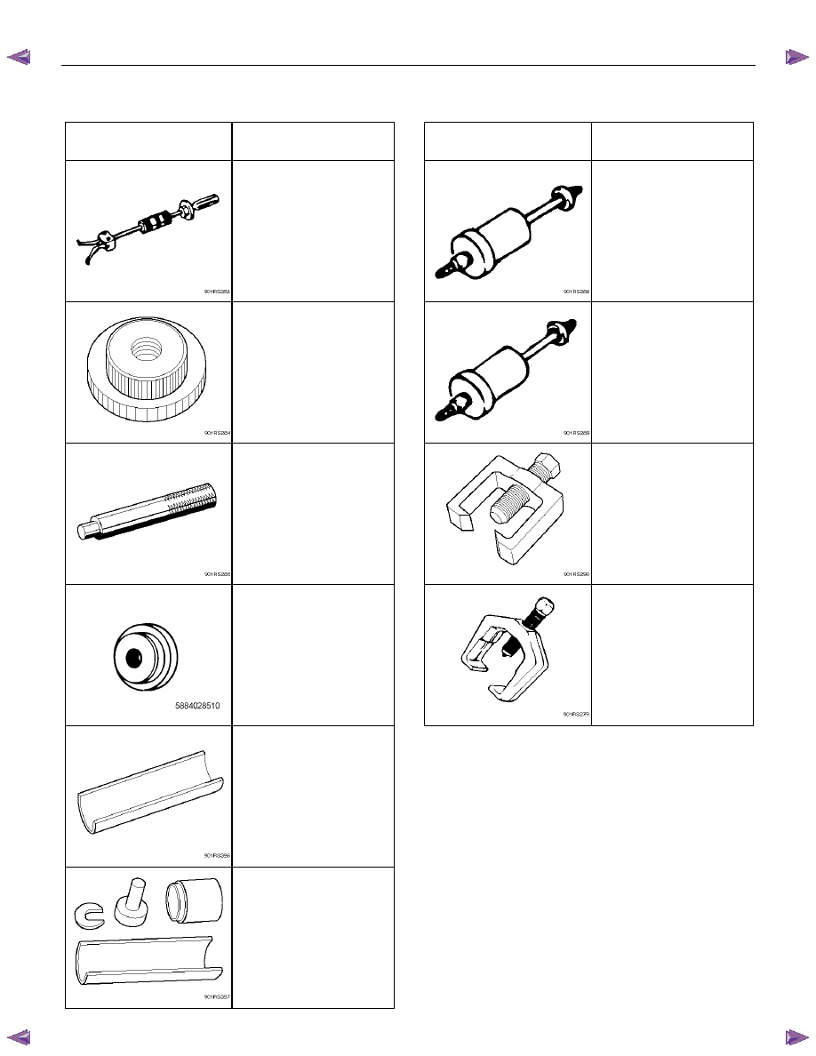
Special Tools (4
××××2 High Ride Suspension, 4××××4)
ILLUSTRATION
PART NO.
PART NAME
ILLUSTRATION
PART NO.
PART NAME
5-8840-2000-0
(J-5822)
Remover; Needle bearing
5-8840-0019-0
(J-23907)
Sliding hammer
(4×4 Model Only)
5-8840-2123-0
(J-36833)
Remover and Installer kit;
Lower arm front bushing
5-8840-2128-0
(J-36838)
Installer; Needle bearing
(4×4 Model Only)
5-8840-2124-0
(J-36834)
Remover and Installer kit;
Lower arm rear bushing
5-8840-0007-0
(J-8092)
Grip
(4×4 Model Only)
5-8840-2121-0
(J-21677-2)
Ball joint remover
5-8840-2851-0
Installer; Oil seal
(4×4 Model Only)
5-8840-2005-0
(J-29107)
Tie-rod end remover
5-8840-2307-0
(J-39376)
Installer; Upper arm
bushing
5-8840-0256-0
(J-29755)
Remover and Installer
Upper arm bushing
3C-54 FRONT SUSPENSION
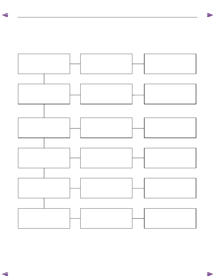
TROUBLESHOOTING
1. VIBRATION, SHOCK, AND SHIMMY OF STEERING WHEEL
Checkpoint Problem
Countermeasure
Check front axle
Check wheel alignment
Check suspension ball joint
Check shock absorber or
attaching nut and bolt
Replace
Adjust
Replace
Replace or retighten
Check steering unit and
linkage
Faulty
Worn
Malfunction or loose
Check upper and lower link
bushings
Replace
Adjust
Worn
Incorrect
OK
OK
OK
NG
NG
NG
NG
NG
NG
OK
OK
Check vehicle trim height
• Improperly adjusted or worn front
wheel bearing.
• Worn or incorrectly adjusted wheel
bearing.
Replace; refer to Section 4C "Front
Wheel Drive"
• Insufficiently tightened steering
gear housing.
• Wear of steering linkage.
• Excessive backlash due to
improper adjustment of the steering
gear box.
• Worn column bearing, weakened
column bearing spring, or loose
clamp.
Replace; refer to Section 3B
"Steering"
• Improper tire pressure.
• Imbalance and deformation of frond
wheel.
• Unevenly worn tire or insufficient
tightening of wheel nuts.
Replace; refer to Section 3E "Wheel
and Tires"
Нет комментариевНе стесняйтесь поделиться с нами вашим ценным мнением.
Текст