Isuzu KB P190. Manual — part 92
FRONT SUSPENSION 3C-47
14. Install cam plate and nut then tighten lower link nut
finger-tight.
NOTE: Apply oil to the thread.
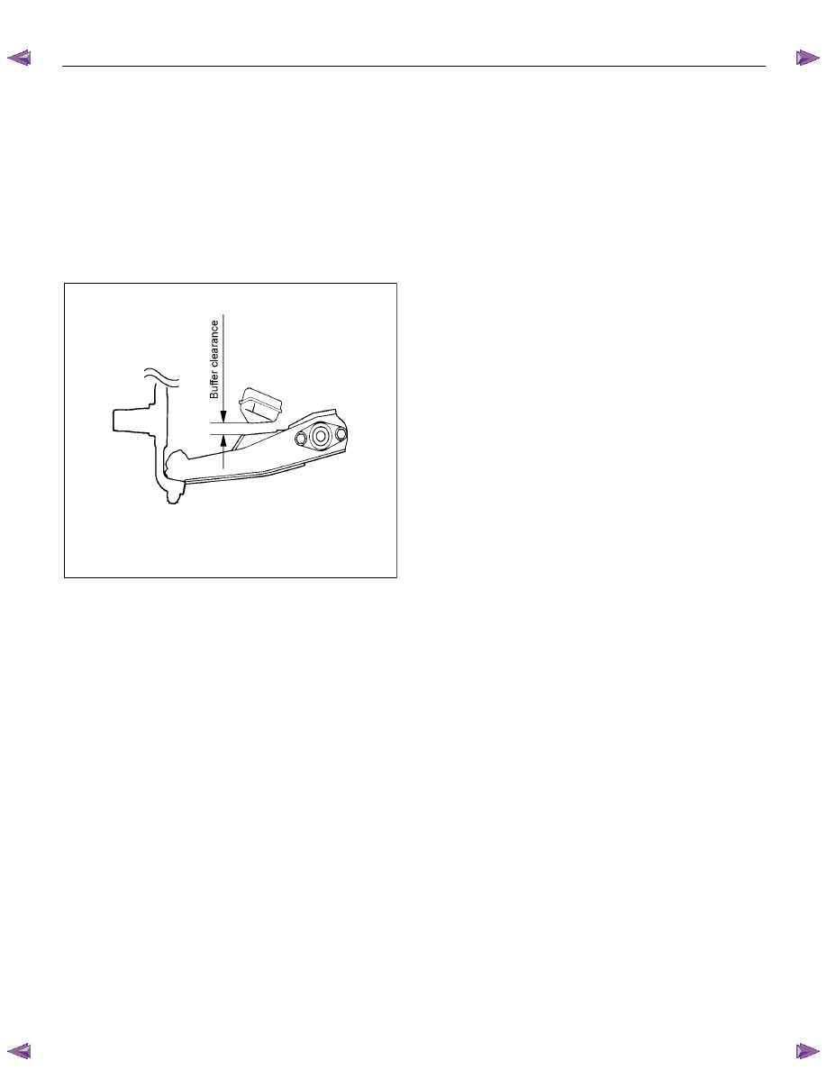
NOTE: Tighten the nut or bolt with the parts in the
position shown in the illustration below.
Buffer clearance: 29.7 mm (1.17 in)
Torque: 186 N
⋅⋅⋅⋅m (19.0 kgf⋅⋅⋅⋅m/137 lb⋅⋅⋅⋅ft)
NOTE: Adjust the trim height. Refer to Front End
Alignment Inspection and Adjustment in Steering
section.
RTW53ASH000301
3C-48 FRONT SUSPENSION
Upper Ball Joint
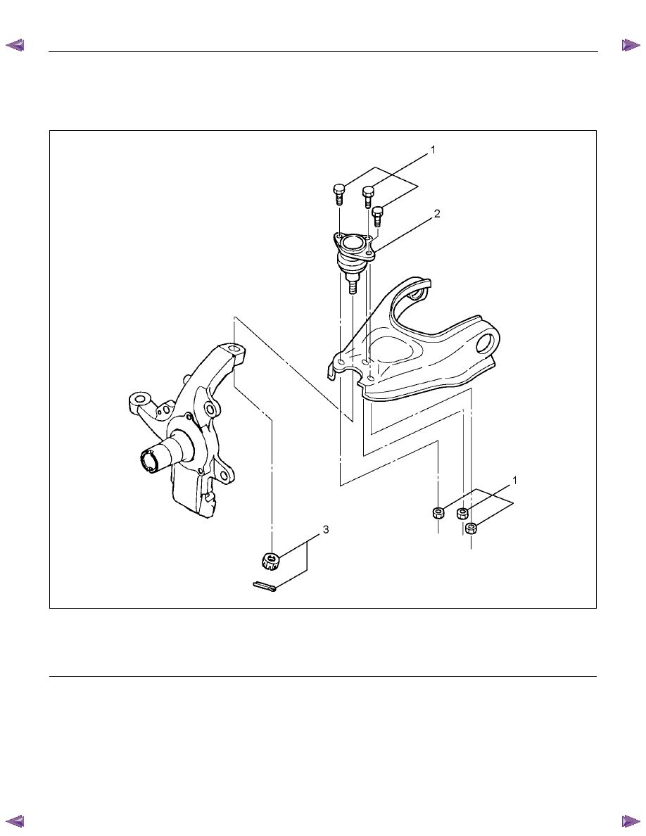
Upper Ball Joint and Associated Parts
RTW440LF001401
Legend
(1) Bolt and Nut
(2) Upper Ball Joint
(3) Nut and Cotter Pin
Removal
1. Raise the vehicle and support the frame with
suitable safety stands.
2. Remove the speed sensor from the knuckle.
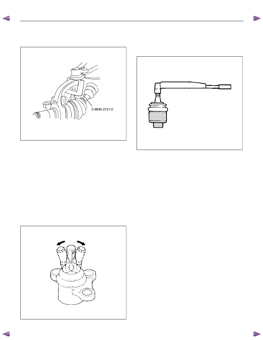
3. Remove upper ball joint nut and cotter pin, then
use remover 5-8840-2121-0 to remove the upper
ball joint from the knuckle.
FRONT SUSPENSION 3C-49
CAUTION: Be careful not to damage the ball joint
boot.
RTW340SH000401
4. Remove bolt and nut.
5. Remove upper ball joint.
Inspection and Repair
Make necessary parts replacement if wear, damage,
corrosion or any other abnormal conditions are found
through inspection.
• Inspect the lower end boot for damage or grease
leak. Move the ball joint as shown in the figure to
confirm its normal movement.
• Inspect screw/taper area of ball for damage.
• If any defects are found by the above inspections,
replace the ball joint assembly with new one.
450RS023
• After moving the ball joint 4 or 5 times, attach nut,
then measure the preload.
Starting torque: 1.3-3.2 N
⋅⋅⋅⋅m (0.13-0.33 kgf⋅⋅⋅⋅m/0.9-
2.4 lb
⋅⋅⋅⋅ft)
450RS024
If the above limits specified are exceeded, replace the
ball joint assembly.
Installation
1. Install upper ball joint.
2. Install bolt and nut, and then tighten them to the
specified torque.
Torque: 57 N
⋅⋅⋅⋅m (5.8 kgf⋅⋅⋅⋅m/42 lb⋅⋅⋅⋅ft)
3. Install nut and cotter pin, and then tighten the nut
to the specified torque with just enough additional
torque to align cotter pin holes. Install new cotter
pin.
Torque: 98 N
⋅⋅⋅⋅m (10.0 kgf⋅⋅⋅⋅m/72 lb⋅⋅⋅⋅ft)
3C-50 FRONT SUSPENSION
Lower Ball Joint
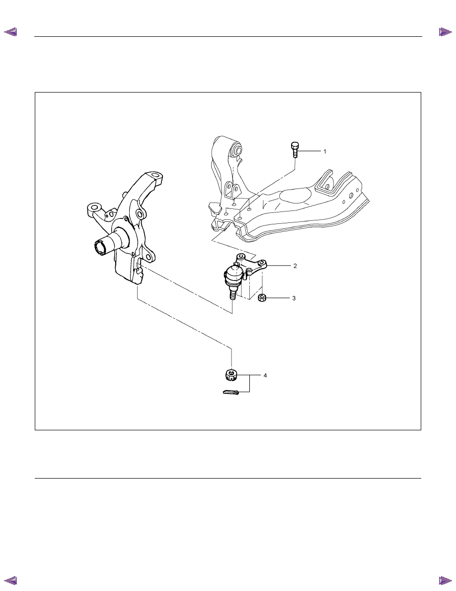
Lower Ball Joint and Associated Parts
RTW340LF001601
Legend
(1) Lower Ball Joint Bolt
(2) Lower Ball Joint
(3) Lower Ball Joint Nut
(4) Nut and Cotter Pin
Removal
1. Raise the vehicle and support the frame with
suitable safety stands.
2. Remove wheel and tire assembly. Refer to Wheel
in this section.
3. Remove the tie-rod end from the knuckle. Refer to
Power Steering Unit in Steering section.
4. Remove the retaining ring from the front axle
driving shaft to release the shaft from hub. Refer to
Front Hub and Disc in Driveline/Axle section.
5. Support lower control arm with a jack.
6. Remove lower ball joint nut and cotter pin, then
use remover 5-8840-2005-0 to remove the lower
ball joint from the knuckle.
Нет комментариевНе стесняйтесь поделиться с нами вашим ценным мнением.
Текст