Isuzu KB P190. Manual — part 91
FRONT SUSPENSION 3C-43
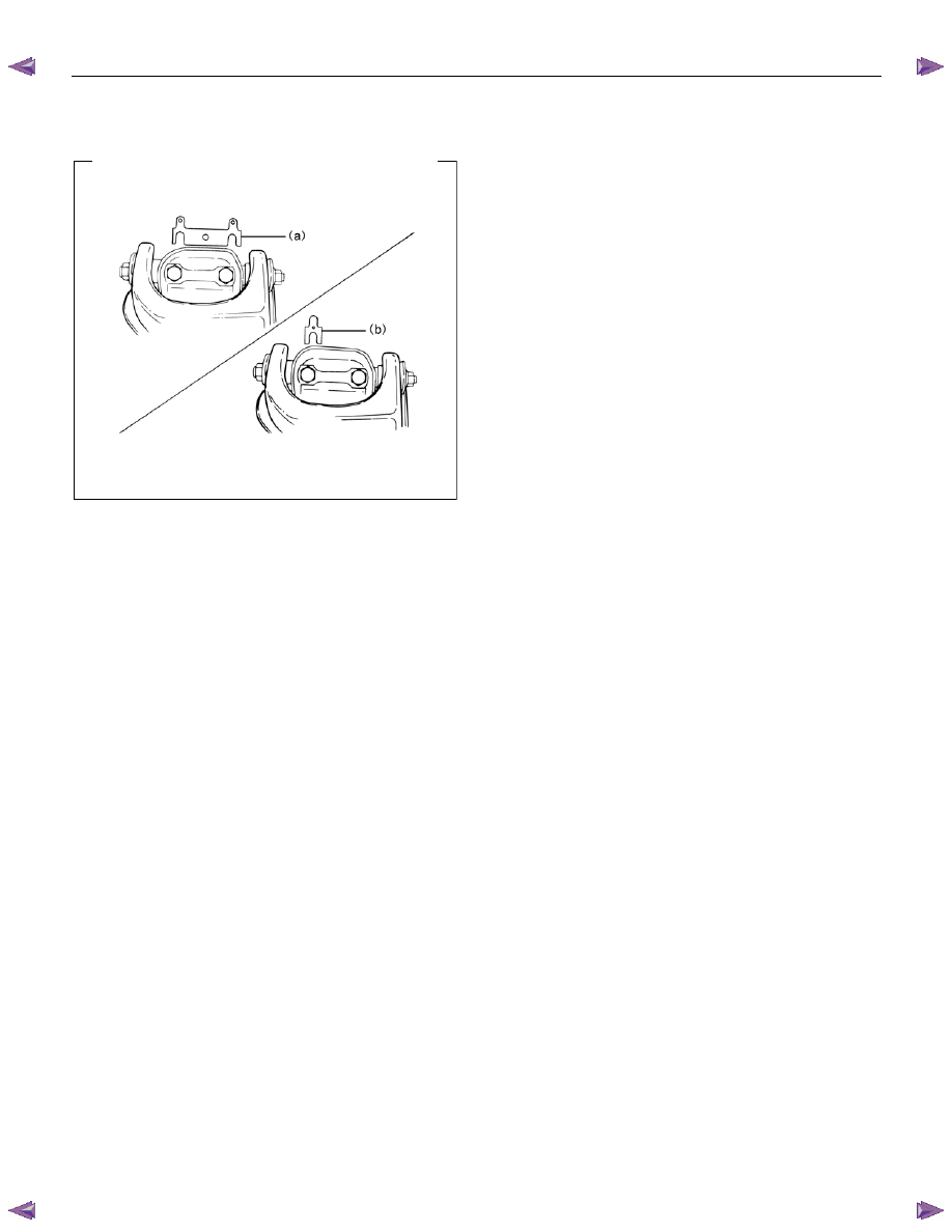
9. Install the camber shims (a) between the chassis
frame and fulcrum pin.
RTW53CSH000201
10. Install nut assembly.
11. Install bolt and plate (a), and then tighten the bolt
to the specified torque.
Torque: 152 N
⋅⋅⋅⋅m (15.5 kgf⋅⋅⋅⋅m/112 lb⋅⋅⋅⋅ft)
NOTE: Apply oil to the thread.
12. Install speed sensor harness.
3C-44 FRONT SUSPENSION
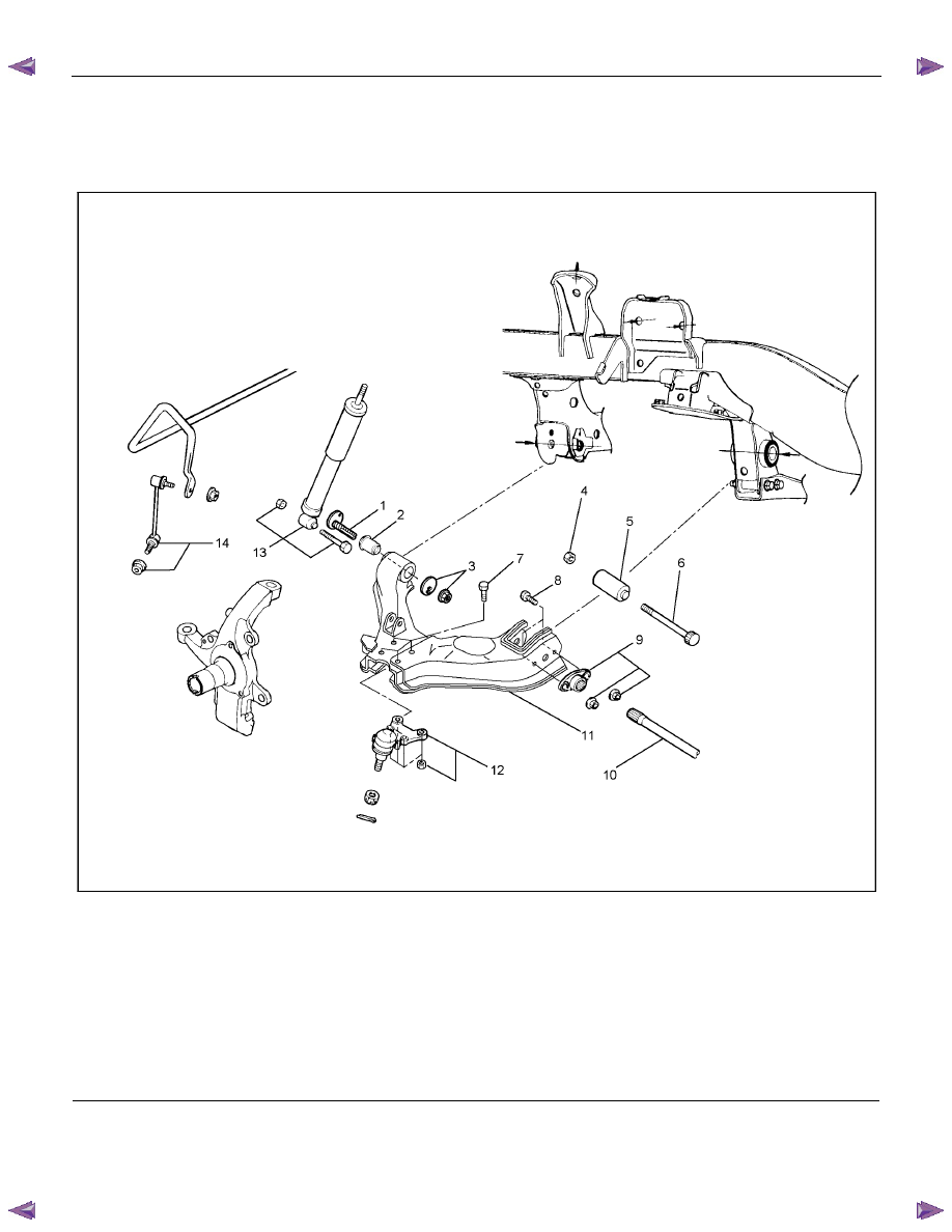
Lower Control Arm
Lower Control Arm and Associated Parts
RTW33CLF000201
Legend
(1) Cam Bolt
(2) Bush, Front
(3) Cam Plate and Nut
(4) Nut, Rear
(5) Bush, Rear
(6) Bolt, Rear
(7) Bolt, Lower Ball Joint
(8) Bolt, Torsion Bar Arm
(9) Torsion Bar Arm Bracket and Nut
(10) Torsion Bar
(11) Lower Control Arm
(12) Lower Ball Joint and Nut
(13) Shock Absorber, Bolt and Nut
(14) Stabilizer Link and Nut
FRONT SUSPENSION 3C-45
Removal
1. Raise the vehicle and support the frame with
suitable safety stands.
2. Remove wheel and tire assembly. Refer to Wheel
in this section.
3. Remove the tie-rod end from the knuckle. Refer to
Power Steering Unit in Steering section.
4. Remove the retaining ring from the front axle
driving shaft to release the shaft from hub. Refer to
Front Hub and Disc in Driveline/Axle section.
5. Support lower control arm with a jack.
6. Remove cam plate and nut.
7. Remove rear nut.
8. Remove torsion bar; refer to Torsion Bar in this
section.
9. Remove torsion bar arm bracket.
10. Disconnect the stabilizer link at the lower control
arm.
11. Remove the shock absorber lower end from the
lower control arm.
12. Remove the lower ball joint from the lower control
arm.
13. Remove cam bolt.
14. Remove rear bolt.
15. Remove lower control arm.
16. Remove torsion bar arm bolt.
17. Remove lower ball joint bolt.
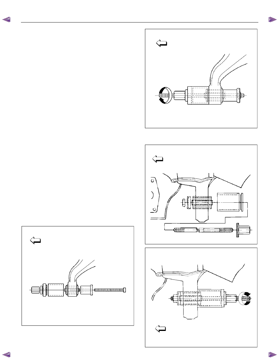
18. Remove front bushing by using remover 5-8840-
2123-0.
Front
901RW154
Front
901RW155
19.
Remove rear bushing by using remover 5-8840-
2124-0.
Front
901RW051
Front
901RW052
3C-46 FRONT SUSPENSION
Inspection and Repair
Make necessary correction or replace parts if wear,
damage, corrosion or any other abnormal condition is
found through inspection.
Check the following parts:
• Lower control arm
• Bushing
Installation
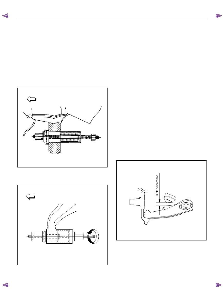
1. Install rear bushing by using installer 5-8840-2124-
0.
Front
901RW053
2. Install front bushing by using installer 5-8840-
2123-0.
Front
901RW156
3. Install lower ball joint bolt.
4. Install torsion bar arm bolt.
5. Install lower control arm.
6. Install rear bolt.
7. Install cam bolt so the hole and projection are
upward.
8. Install lower ball joint and tighten it to the specified
torque.
Torque: 127 N
⋅⋅⋅⋅m (13.0 kgf⋅⋅⋅⋅m/94 lb⋅⋅⋅⋅ft)
9. Install shock absorber and tighten it to the
specified torque.
Torque: 93 N
⋅⋅⋅⋅m (9.5 kgf⋅⋅⋅⋅m/69 lb⋅⋅⋅⋅ft)
10. Install stabilizer link and tighten it to the specified
torque.
Torque: 50 N
⋅⋅⋅⋅m (5.1 kgf⋅⋅⋅⋅m/37 lb⋅⋅⋅⋅ft)
11. Install torsion bar arm bracket and tighten it to the
specified torque.
Torque: 116 N
⋅⋅⋅⋅m (11.8 kgf⋅⋅⋅⋅m/85 lb⋅⋅⋅⋅ft)
12.
Install Torsion bar; refer to Torsion Bar in this
section.
13. Install rear nut and tighten nut finger-tight.
NOTE: Apply oil to the thread.
NOTE: Tighten the nut or bolt with the parts in the
position shown in the illustration below.
Buffer clearance: 29.7 mm (1.17 in)
Torque: 235 N
⋅⋅⋅⋅m (24.0 kgf⋅⋅⋅⋅m/174 lb⋅⋅⋅⋅ft)
RTW53ASH000301
Нет комментариевНе стесняйтесь поделиться с нами вашим ценным мнением.
Текст