Isuzu KB P190. Manual — part 1193
Manual Transmission (MUX) 7B1-53
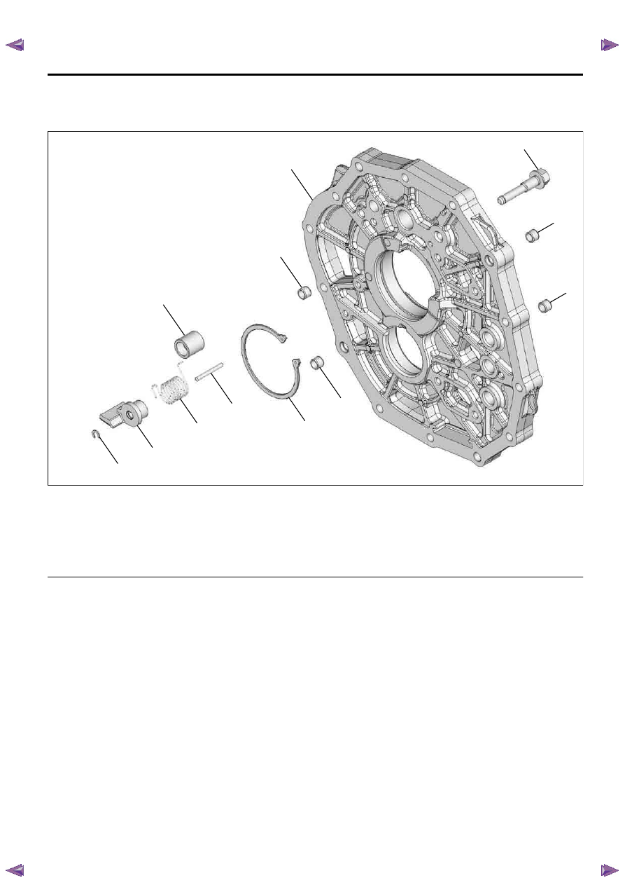
Intermediate Plate Assembly
Component
Legend
1. Intermediate plate
2. Reverse inhibitor bolt
3. Dowel
4. Input middle bearing snap ring
5. Straight pin
6. Reverse inhibitor spring
7. Reverse inhibitor
8. Reverse inhibitor snap ring
9. Linear ball bearing
Removal
1. Remove the reverse inhibitor snap ring.
2. Remove the reverse inhibitor and spring.
3. Remove the reverse inhibitor bolt.
4. Remove the straight pin.
5. Remove the linear ball bearing.
6. Remove the four dowels.
7. Use a pair of snap ring pliers to remove the input
middle bearing snap ring.
Installation
1. Use a pair of snap ring pliers to install the new
input middle bearing snap ring.
• Never reinstall the used snap ring.
2. Install the four dowels.
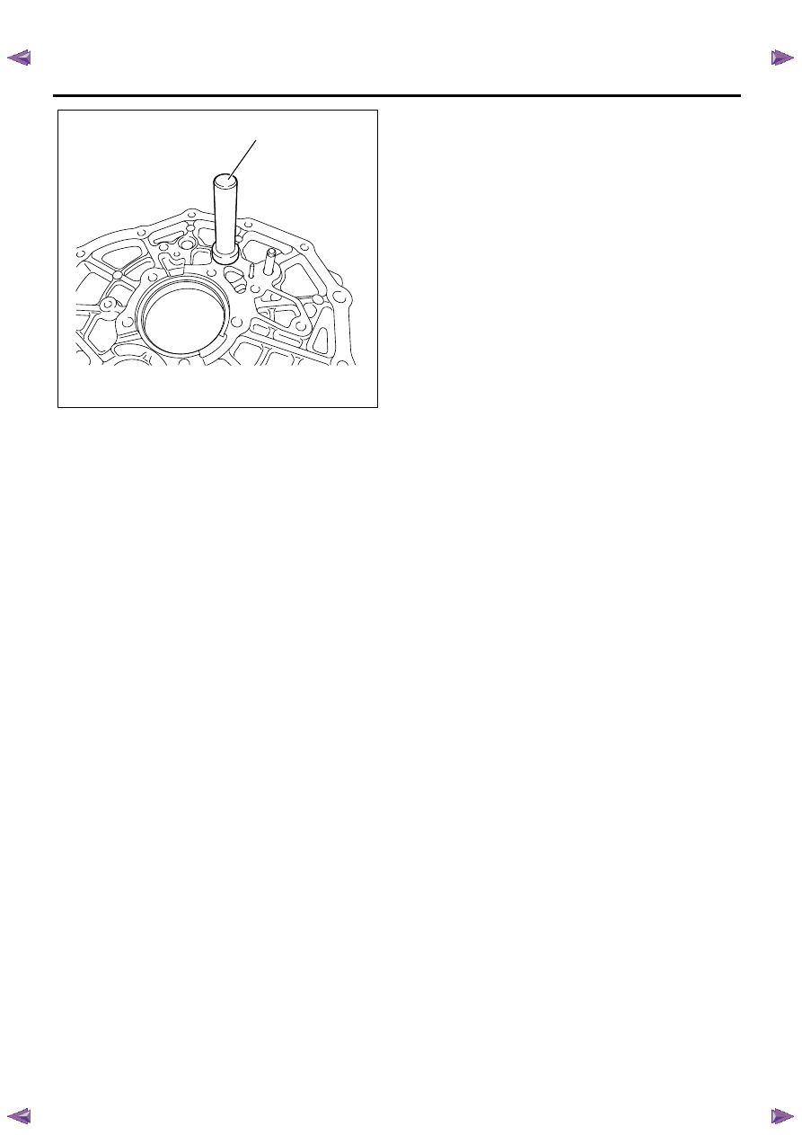
3. Use the installer 5-8840-2848-0 (1) to install the
linear ball bearing.
Notice:
• The bearing to be pressed fit to boss face.
• The bearing must be pressed at marked side.
RTW77BMF001001
9
3
1
2
3
3
3
4
5
6
7
8
7B1-54 Manual Transmission (MUX)
4. Install the straight pin.
5. Install the reverse inhibitor bolt.
• Tighten the reverse inhibitor bolt to the
specified torque.
Torque: 36 N
⋅m (3.7 kgf⋅m/27 lb⋅ft)
6. Install the reverse inhibitor and spring.
7. Install the new reverse inhibitor snap ring.
• Never reinstall the used snap ring.
Notice:
The snap ring must be assembled in groove of bolt
surely.
RTW77BSH002701
1
Manual Transmission (MUX) 7B1-55
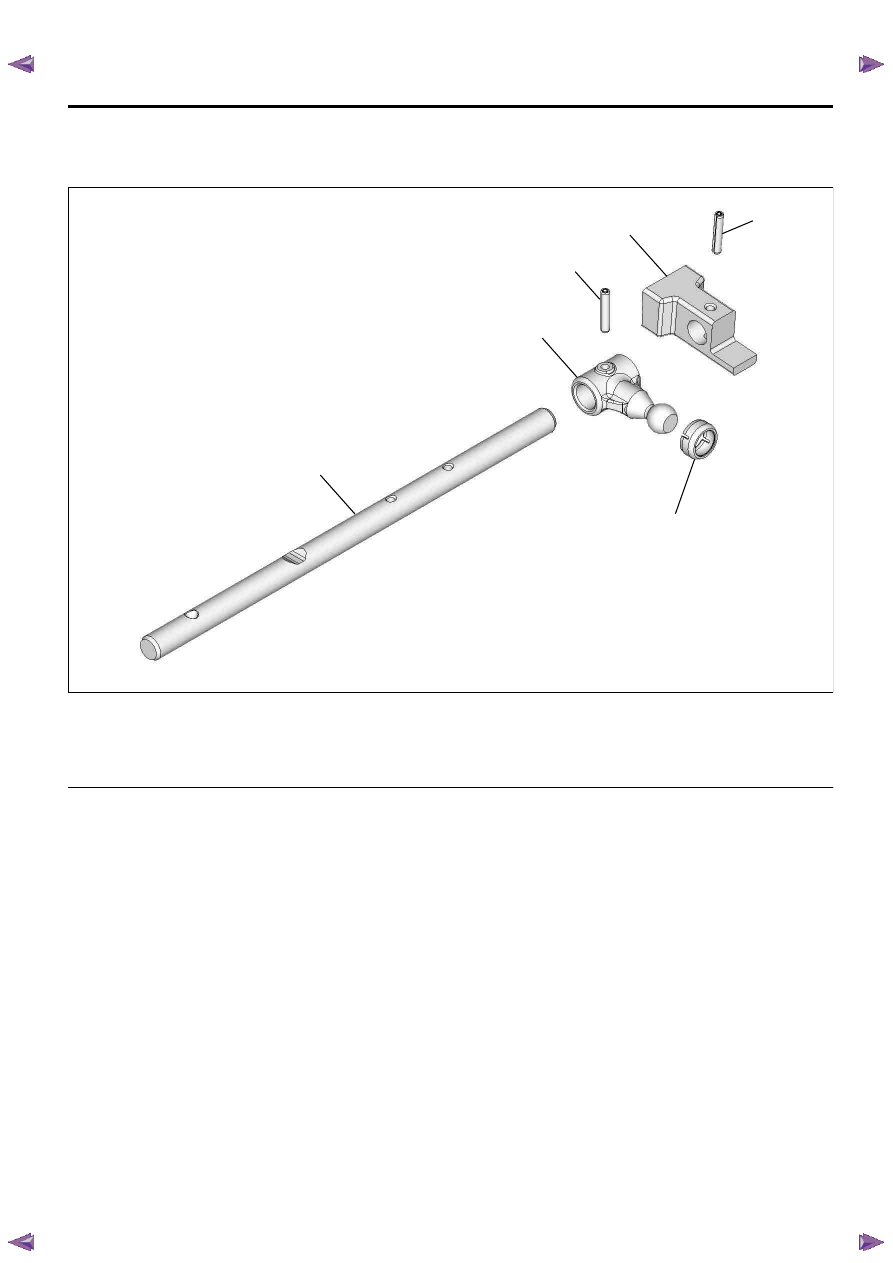
Control Rod Assembly
Component
Legend
1. Control rod
2. Control unit lever
3. Control unit lever spring pin
4. Detent shift block
5. Detent shift block spring pin
6. Shift control seat
Removal
1. Remove the shift control seat.
2. Use a spring pin remover to remove the spring pin
and the control unit lever.
3. Use a spring pin remover to remove the spring pin
and the detent shift block.
Installation
1. Install the detent shift block and the new spring pin.
• Never reinstall the used spring pin.
Notice:
• When assembled, vertical direction of block exists.
• The spring pin must be drive in to hole of end
surface of block surely.
2. Install the control unit lever and the new spring pin.
• Never reinstall the used spring pin.
Notice:
The spring pin must be drive in to hole of end surface of
lever surely.
3. Install the shift control seat.
• Apply grease to tip of sphere of lever and seat.
RTW77BMF001101
1
2
3
4
5
6

7B1-56 Manual Transmission (MUX)
5th-Reverse Shift Block Assembly
Component
Legend
1. 5th-reverse shift lever
2. 5th-reverse shift block
3. Straight pin
Removal
1. Remove the straight pin and the 5th-reverse shift
lever.
Notice:
Make sure to remove the straight pin (2) in the direction
of 4.5 mm (0.177 in) diameter bore (1) side.
Installation
1. Install the 5th-reverse shift lever and the straight
pin.
Notice:
• Install the straight pin (2) from 4.5 mm (0.177 in)
diameter bore (1) side, and adjust the setting
position to make the end of straight pin flush with
the end of the shift block.
• Installation direction of the lever to be not
misassembled.
RTW77BSF000601
1
2
3
RTW77BSH007301
1
2
RTW77BSH007401
1
2
Нет комментариевНе стесняйтесь поделиться с нами вашим ценным мнением.
Текст