Isuzu KB P190. Manual — part 23
1-58 HEATER AND AIR CONDITIONING
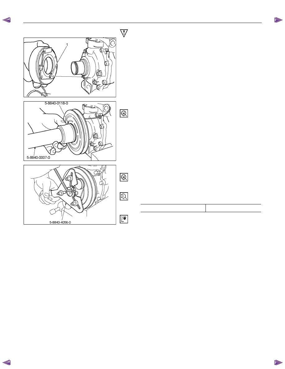
Important Operations - Reassembly
RTW510SH001001
2. Field Coil
Installation field coil.
• Align the located portion (1) of the clutch coil and
compressor.
RTW510SH001101
4. Pulley Assembly
Using pulley installer and drive handle to install the pulley
assembly.
Pulley Installer: 5-8840-0118-0 (J-33940)
Drive Handle: 5-8840-0007-0 (J-8092)
RTW510SH000701
8. Drive Plate Bolt
Using drive plate holder to prevent the drive plate from
rotating.
Drive Plate Holder: 5-8840-4056-0 (J-37872)
Tighten the bolt to the specified torque.
N
⋅m (kgf⋅m/Ib⋅in)
Torque 13
(1.3/113)
After tightening the bolt, check to be sure the pulley rotates
smoothly.
HEATER AND AIR CONDITIONING 1-59
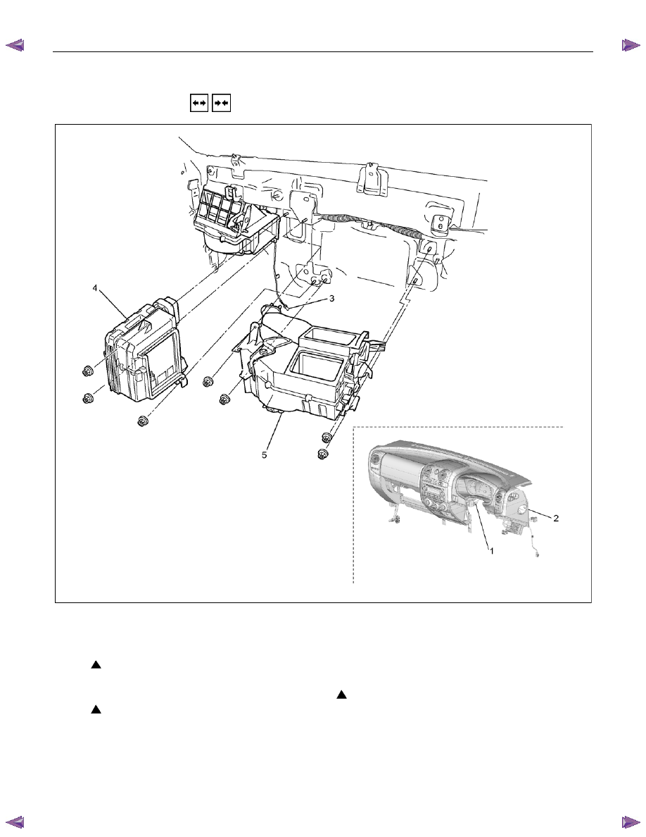
HEATER UNIT
REMOVAL AND INSTALLATION
This illustration is based on RHD model
RTW710LF001601
Removal Steps
1. Control cable
2. Instrument panel assembly and cross
beam
3. Electronic thermostat connector
4. Evaporator or duct
5. Heater unit
Installation steps
5. Heater unit
4. Evaporator or duct
3. Electronic thermostat connector
2. Instrument panel assembly and cross
beam
1. Control cable

1-60 HEATER AND AIR CONDITIONING
Important Operations – Removal
2. Instrument Panel Assembly and Cross Beam.
Refer to SECTION 10 “INSTRUMENT PANEL”.
4. Evaporator or Duct
Refer to “EVAPORATOR” or “DUCT” in this section.
Important Operation - Installation
2. Instrument Panel Assembly and Cross Beam
Adjust the heater control cables.
Refer to "CONTROL LEVER ASSEMBLY" in this section.

HEATER AND AIR CONDITIONING 1-61
DISASSEMBLY AND REASSEMBLY
This illustration is based on RHD model
RTW310LF001401
Disassembly Steps
1. Attaching screw
2. Main link-side
3. Sub link-side
4. Mode rod
5. Holder rod
6. Mode lever
7.
DEF/FOOT-spring
8.
VENT-spring
9. Heater box clip
10. Attaching screws
11. Foot duct
12. FOD H/Pipes seal
13. Heater core clamp
14. Heater core
15. Mix lever (2)
16. Mix lever (1)
17. Control cable clamp
18. Attaching screws
19. Upper case
20. Lower case
21. DEF/FOOT door
22. VENT door
23. Mix door
24. Control cable clamp
Reassembly Steps
24. Control cable clamp
23. Mix door
22. VENT door
21. DEF/FOOT door
20. Lower case
19. Upper case
18. Attaching screws
17. Control cable clamp
16. Mix lever (1)
15. Mix lever (2)
14. Heater core
13. Heater core clamp
12. FOD H/Pipes seal
11. Foot duct
10. Attaching screws
9. Heater box clip
8.
VENT-spring
7.
DEF/FOOT-spring
6. Mode lever
5. Holder rod
4. Mode rod
3. Sub link-side
2. Main link-side
1. Attaching screw
Нет комментариевНе стесняйтесь поделиться с нами вашим ценным мнением.
Текст