Isuzu KB P190. Manual — part 22
1-54 HEATER AND AIR CONDITIONING
OIL RETURN OPERATION
There is close affinity between the oil and the refrigerant.
During normal operation, part of the oil recirculates with the
refrigerant in the system.
When checking the amount of oil in the system, or replacing
any component of the system, the compressor must be run in
advance for oil return operation. The procedure is as follows:
1) Open the all doors and engine hood.
2) Start the engine and A/C switch is "ON" and Set the fan
control knob at its highest position.
3) Run the compressor for more than 20 minutes between
800 and 1,000 rpm in order to operate the system.
4) Stop the engine.
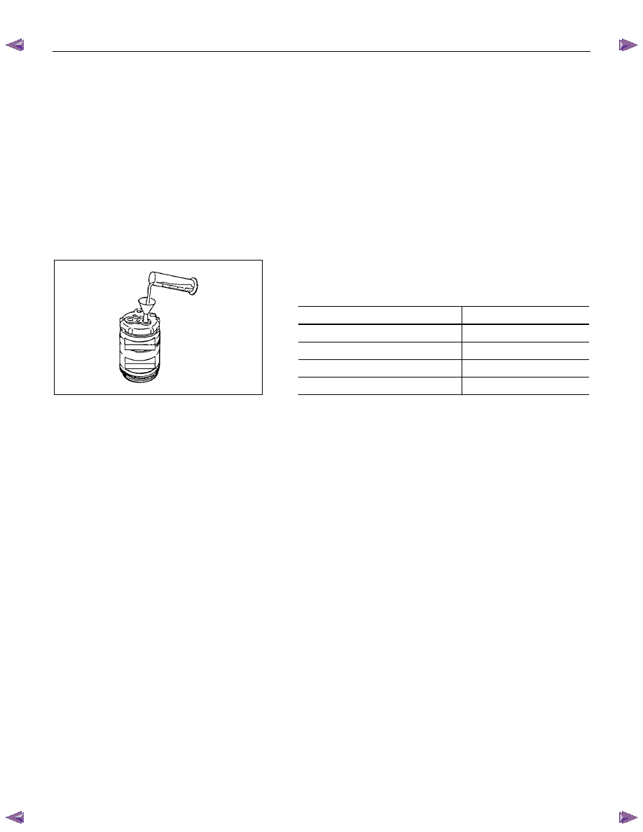
REPLACEMENT OF COMPONENT PARTS
When replacing system component parts, supply the following
amount of oil to the component parts to be installed.
Component parts to be installed
Amount of oil
Evaporator 50
cm
3
(1.41 lmp fl oz)
Condenser 30
cm
3
(0.84 lmp fl oz)
Receiver/drier 30
cm
3
(0.84 lmp fl oz)
Refrigerant line (One piece)
10 cm
3
(0.28 lmp fl oz)
Refrigeration oil must be replenished if more than two parts
are removed at the same time. After installing these
components, check compressor oil.
HEATER AND AIR CONDITIONING 1-55
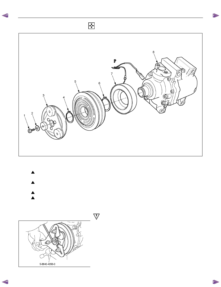
DISASSEMBLY
This illustration is based on the 4J engine model
RTW510MF000301
Disassembly Steps
1. Drive plate bolt
2. Plain washer
3. Drive plate
4. Snap ring
5. Pulley assembly
6. Snap ring
7. Field coil
8.
Compressor
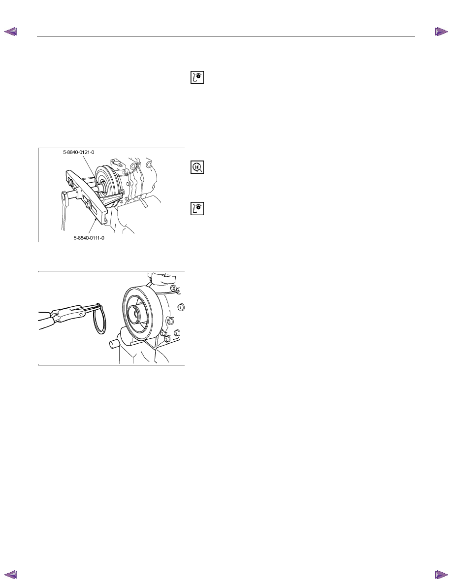
Important Operations - Disassembly
RTW510SH000701
1. Drive Plate Bolt
Using drive plate holder to prevent the drive plate from
rotating, then remove the bolt.
Drive Plate Holder: 5-8840-4056-0 (J-37872)
1-56 HEATER AND AIR CONDITIONING
3. Drive Plate
Remove the drive plate.
If the frictional surface shows signs of damage due to
excessive heat, the drive plate and pulley should be
replaced.
RTW510SH000801
5. Pulley Assembly
Using pulley puller pilot and pulley puller to remove the
pulley assembly.
Pulley Puller Pilot: 5-8840-0121-0 (J-33943)
Pulley Puller:
5-8840-0111-0 (J-8433)
Check the appearance of the pulley assembly. If the
frictional surface of the pulley shows signs of excessive
grooving due to slippage, both the pulley and drive plate
should be replaced. The frictional surfaces of the pulley
assembly should be cleaned with a suitable solvent before
reinstallation.
RTW510SH000901
6. Snap ring
Using snap ring pliers to remove the snap ring.
HEATER AND AIR CONDITIONING 1-57
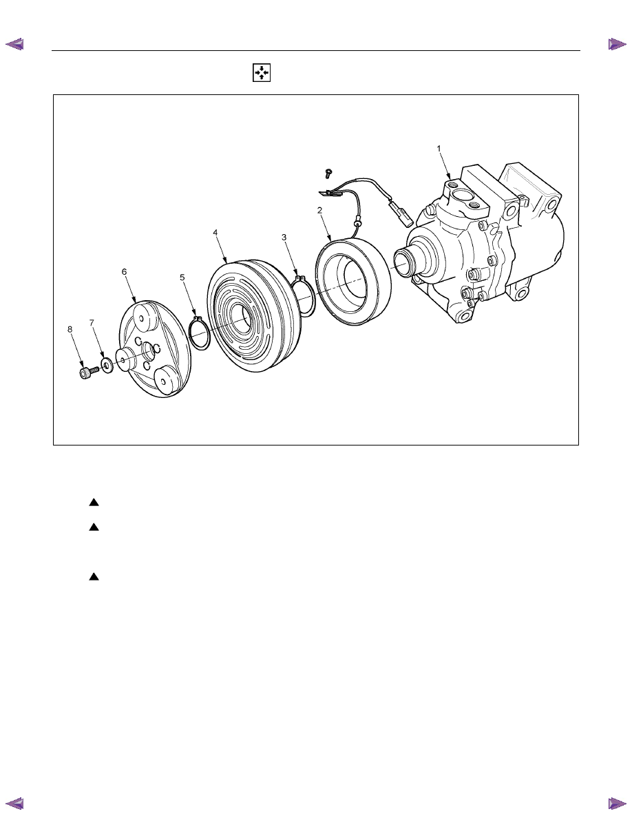
REASSEMBLY
This illustration is based on the 4J engine model
RTW510MF000401
Reassembly Steps
1.
Compressor
2. Field coil
3. Snap ring
4. Pulley assembly
2. Snap ring
3. Drive plate
7. Plain washer
8. Drive prate bolt
Нет комментариевНе стесняйтесь поделиться с нами вашим ценным мнением.
Текст